
Detachable electric power tunnel cable safety supporting device

A power tunnel and safety support technology is applied in the field of detachable cable safety support devices for power tunnels, which can solve the problems of inconvenient welding construction, grounding failure, slow construction speed, etc. quick effect

Inactive Publication Date: 2018-05-25
STATE GRID SHANDONG ELECTRIC POWER COMPANY WEIFANG POWER SUPPLY +1
View PDF10 Cites 2 Cited by
  • Summary
  • Abstract
  • Description
  • Claims
  • Application Information

AI Technical Summary

Problems solved by technology

The disadvantages of the first method are: 1. When pouring concrete, the shape of the embedded parts is irregular and it is easy to deviate from the fixed position, which brings inconvenience to the installation of the cable bracket; 2. The cable bracket needs to be close to the embedded parts to be welded, and the two The space is relatively narrow after the person is close to it, the welding construction is inconvenient, the construction speed is slow, and the welding firmness is difficult to guarantee; 3. The embedded parts are pre-embedded on site when the power tunnel is built, and the surface is easily adhered to mud or oil. As a result, a water seepage channel is formed after pouring concrete, which causes water seepage in the cable tunnel after a long time; 4. Since the cable bracket is welded on the embedded part, it is very inconvenient to maintain or disassemble, and it is difficult to reinstall it after forcible disassembly. Utilization causes waste; 5. The connection of the grounding part is unreliable, resulting in grounding failure, which seriously threatens the operation safety of the staff

Method used


Image

  • Detachable electric power tunnel cable safety supporting device
  • Detachable electric power tunnel cable safety supporting device
  • Detachable electric power tunnel cable safety supporting device

Examples


Embodiment Construction

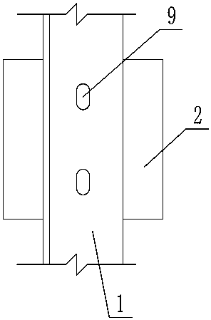
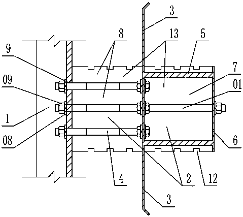
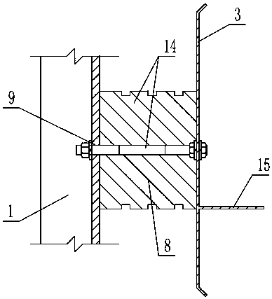
[0032] As shown in the figure, the detachable cable safety support device for power tunnels includes a frame body 1 and embedded parts 2, and the embedded parts include an upper embedded part 13 and a lower embedded part 14, and the embedded parts include vertically arranged The water retaining plate 3, the outer side of the middle part of the water retaining plate of the upper embedded part is fixed with a grounding plate 6 parallel to the water retaining plate through the connecting column 5, and an outer wrapping connecting column is fixed between the grounding plate and the water retaining plate Concrete block 7, the central part of the water retaining plate of the upper embedded part is installed with a central column 01 extending vertically to the inside and outside of the water retaining plate. The copper layer 03 on the ground plate is provided with a rear hole 04 corresponding to the center column, and the rear end of the center column is tightened with a rear gasket 0...


PUM


Abstract

The invention discloses a detachable electric power tunnel cable safety supporting device. The device comprises a rack body, an upper embedded part and a lower embedded part, wherein the embedded parts respectively comprise a vertically-arranged water blocking plate, an outer side of a middle portion of the water blocking plate of the upper embedded part is fixedly provided with a ground plate through a connection column, the ground plate and the water blocking plate are arranged parallelly, an outer concrete block for wrapping the connection column is fixedly arranged between the ground plateand the water blocking plate, a middle portion of the water blocking plate of the lower embedded part is fixedly provided with a horizontally-arranged calibration plate, inner sides of the middle portions of the water blocking plates of the embedded parts are perpendicularly and fixedly provided with bolts, inner sides of the water blocking plates are provided with inner concrete blocks fixedly arranged on inner walls of the bolts and the water blocking plates, the inner concrete blocks and the outer concrete block are cuboids of which circumferential walls are arranged in a parallel mode, abottom surface of the calibration plate is level with bottom surfaces of the inner concrete blocks, and the rack body is provided with bar-shaped holes corresponding to tail ends of the bolts. The device has advantages of stable concrete casting position, accurate mounting, fast construction speed, reliable supporting, good sealing, non-easy water seepage, long service life, convenient dismountingand maintenance and low use cost.

Description

technical field [0001] The invention relates to a detachable cable safety support device for an electric power tunnel. Background technique [0002] With the acceleration of the modernization process of the urban power supply system, the power transmission method has gradually been replaced by the underground power tunnel transmission with a low failure rate and high safety. The underground power tunnel transmission method is mainly to construct a tunnel for laying power wires underground, and lay the power cables in the power tunnel through the cable support device in accordance with the design specifications of the power system. [0003] In practical applications, the cable support device generally uses a cable support (support) frame fixed on the side wall of the power tunnel to support the power cable. There are generally two ways to install the cable support frame on the side wall of the power tunnel. One is to bury the embedded parts on the trench wall of the power tu...

Claims


Application Information

Patent Timeline
IPC IPC(8): H02G9/08
CPCH02G9/08
Inventor 赵星辰牛学娇于友军朱秀娟田琦马国强蔡丽佳刘政刘文光
Owner STATE GRID SHANDONG ELECTRIC POWER COMPANY WEIFANG POWER SUPPLY
Learn More