Laser rust remover and rust removing method thereof

A technology of laser rust removal and laser beam, which is applied in the direction of laser welding equipment, cleaning methods and appliances, chemical instruments and methods, etc., can solve the problems of parts burn, high cost, and different shapes, so as to achieve convenient placement and avoid errors , the effect of reducing the volume

Active Publication Date: 2018-05-29
GUANGZHOU NEW CKLASER CO LTD
View PDF8 Cites 4 Cited by
  • Summary
  • Abstract
  • Description
  • Claims
  • Application Information

AI Technical Summary

Problems solved by technology

[0002] The derusting process is a very important step for the processing industry. Many enterprises need to use this process in the process of processing or assembly, while the traditional derusting is mostly manual derusting, which is very inefficient. , but the advantage is that some parts with uneven surfaces can be carefully removed, but with the development of society, the competition is becoming more and more fierce, and the artificial rust removal in the past can no longer meet the needs of the market. In order to solve this situation, some technologies have emerged Improvements in aspects, such as CN 201610986098.1 patent for laser derusting equipment and its control method, by setting specific structures on the workbench, the laser can derust the end faces or tooth surfaces of parts, although this technical solution can improve some derusting The efficiency of rust, but there are still the following defects,
[0003] 1. Move the laser through the two-axis positioner on the workbench to derust the parts. This method is not only costly, but also requires high precision of the two-axis positioner. If there is a slight deviation, it will It will burn the parts next to the rust;
[0004] 2. Because the rust is formed naturally, the shape is different. The equipment needs to manually calibrate the rust removal part before the rust removal, which is time-consuming and laborious, and there is a lack of monitoring of the work level and process during the rust removal process.

Method used


Image

  • Laser rust remover and rust removing method thereof
  • Laser rust remover and rust removing method thereof
  • Laser rust remover and rust removing method thereof

Examples


Embodiment Construction

[0048] The specific embodiments of the present invention will be further described below in conjunction with the accompanying drawings.

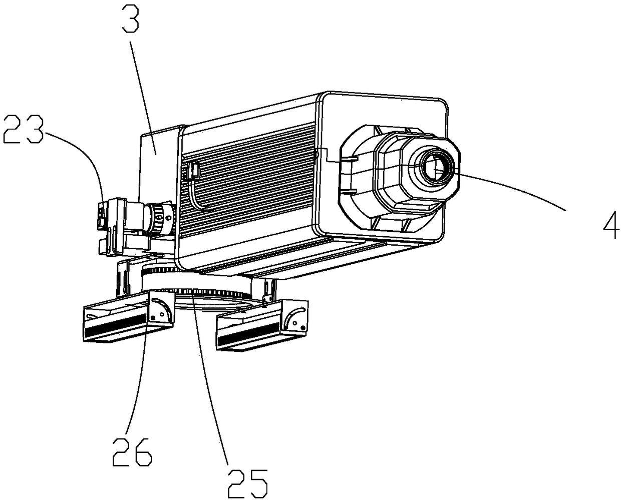
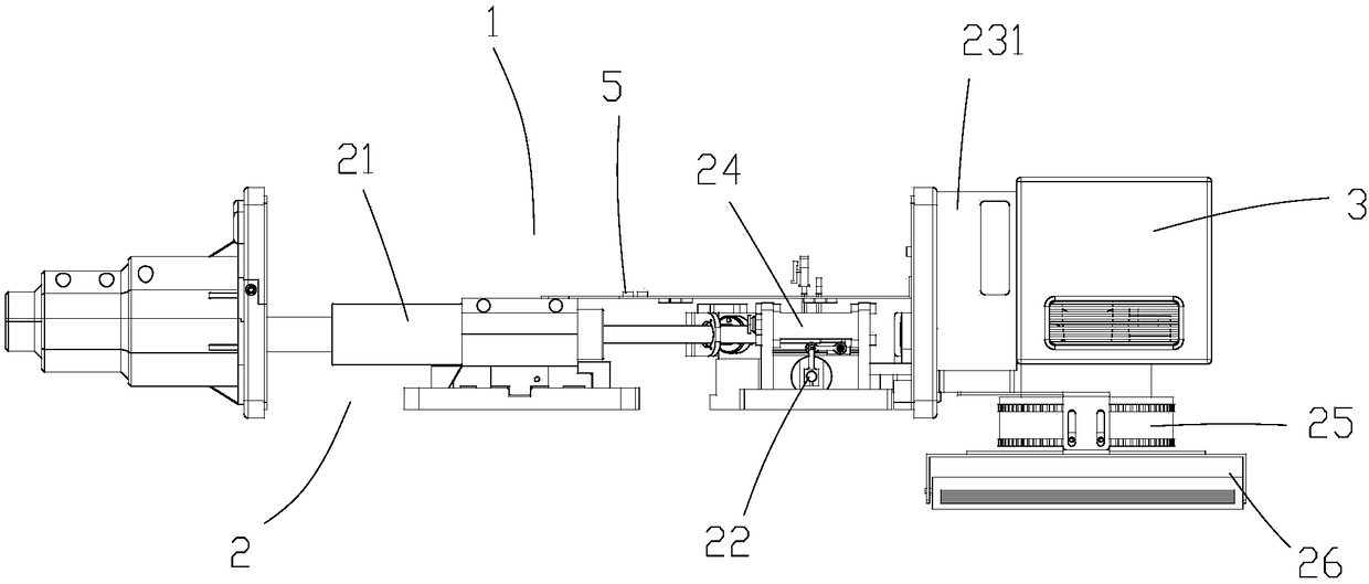
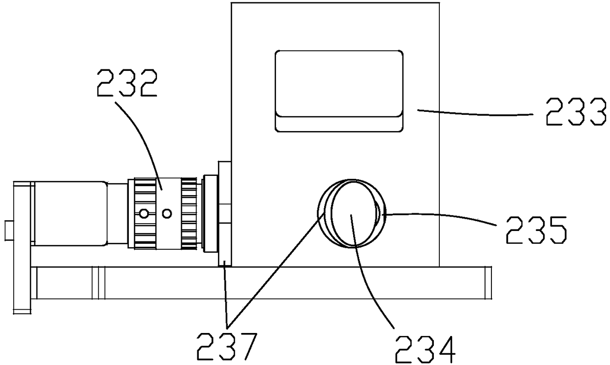
[0049] Such as Figures 1 to 8 As shown, this embodiment provides a laser descaling machine, including a wire feeder 4 connected to one end of the cavity and coaxial with it, and a vibrating mirror part 3 connected to the other end of the cavity. The axis is the upper cavity 1 and the lower cavity 2 formed by the division of the dividing line. There is a partition 5 between the upper cavity 1 and the lower cavity 2. The upper cavity 1 is provided with a plurality of wire feeders 4 extending into the upper cavity. The circuit wires of the chamber, a plurality of said circuit wires extend into the vibrating mirror part 3 from the other end of the upper chamber 1, and a transmitter 21, a zoom Device 22 and camera system 23;

[0050] The input end of the transmitter 21 is connected to the circuit line in the wire feeder 4, and the output end f...


PUM


Abstract

According to the technical scheme, a line feeder connected with one end of a cavity and coaxial with the cavity and a galvanometer part connected with the other end of the cavity are included. It is characterized in that the cavity comprises an upper cavity body and a lower cavity body formed due to dividing with the axis as the boundary; a plurality of circuit lines entering the upper cavity bodyfrom the line feeder are arranged in the upper cavity body; the circuit lines stretch into the galvanometer part from the other end of the upper cavity body; in the direction, close to the galvanometer part from the line feeder, in the lower cavity body is provided with an emitter, a zooming device and a photographic system; and an air cooler and a field mirror are further arranged in the lower cavity body. The device is efficient, convenient and fast, long in service life and favorable for rust removing on various parts.

Description

technical field [0001] The invention relates to the technical field of derusting equipment, in particular to a laser derusting machine. Background technique [0002] The derusting process is a very important step for the processing industry. Many enterprises need to use this process in the process of processing or assembly, while the traditional derusting is mostly manual derusting, although the efficiency is very low. , but the advantage is that some parts with uneven surfaces can be carefully removed, but with the development of society, the competition is becoming more and more fierce, and the artificial rust removal in the past can no longer meet the needs of the market. In order to solve this situation, some technologies have emerged Improvements in aspects, such as CN 201610986098.1 patent for laser derusting equipment and its control method, by setting specific structures on the workbench, the laser can derust the end faces or tooth surfaces of parts, although this te...

Claims


Application Information

Patent Timeline
Patent Type & Authority Applications(China)
IPC IPC(8): B23K26/352B23K26/064B23K26/03B23K26/046B23K26/70B08B7/00
CPCB08B7/0042B23K26/032B23K26/046B23K26/064B23K26/352B23K26/703
Inventor 徐强
Owner GUANGZHOU NEW CKLASER CO LTD
Why Eureka
Try Eureka