
Laminated assembly cutting die

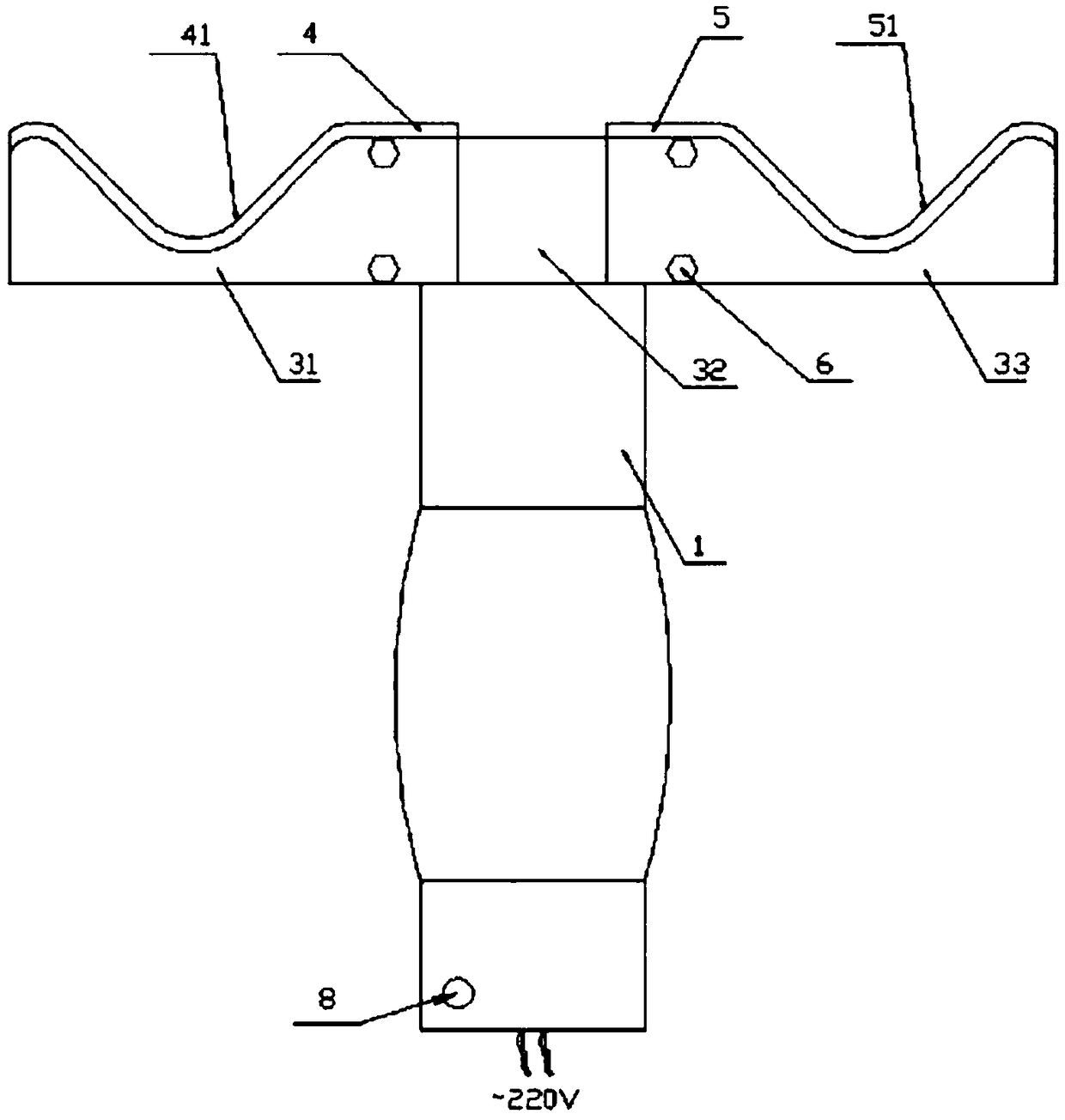
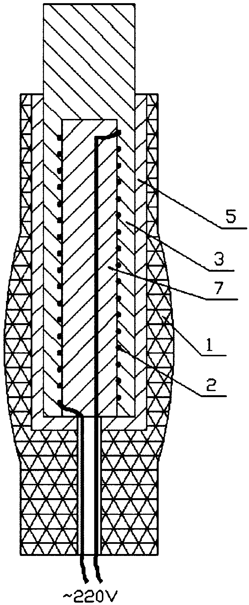
A technology of laminated components and molds, which is applied in metal processing and other directions, can solve the problems of easy wear of blades and reduce the efficiency of cutting edges, and achieve the effects of improving work efficiency, reducing blade loss, and reducing replacement frequency

Inactive Publication Date: 2018-05-29
余姚市宏硕模具制造有限公司
View PDF0 Cites 0 Cited by
  • Summary
  • Abstract
  • Description
  • Claims
  • Application Information

AI Technical Summary

Problems solved by technology

When cutting the edge, the handle is used to push the blade to cut the edge of the laminated component, but this solution has disadvantages: the blade is very easy to wear and tear due to the blade cutting alone, and the blade needs to be replaced frequently during the edge cutting process, which reduces the Trimming efficiency

Method used


Image

  • Laminated assembly cutting die
  • Laminated assembly cutting die
  • Laminated assembly cutting die

Examples


Embodiment Construction

[0027] It should be noted that, in the case of no conflict, the embodiments of the present invention and the features in the embodiments can be combined with each other.

[0028] In describing the present invention, it should be understood that the terms "center", "longitudinal", "transverse", "upper", "lower", "front", "rear", "left", "right", " The orientations or positional relationships indicated by "vertical", "horizontal", "top", "bottom", "inner" and "outer" are based on the orientations or positional relationships shown in the drawings, and are only for the convenience of describing the present invention and Simplified descriptions, rather than indicating or implying that the device or element referred to must have a particular orientation, be constructed and operate in a particular orientation, and thus should not be construed as limiting the invention. In addition, the terms "first", "second", etc. are used for descriptive purposes only, and should not be understood ...


PUM


Abstract

The invention discloses a laminated assembly cutting die. The cutting die comprises a handle, electric heating wires, a heat conductor, a first blade, a second blade and bolts; the heat conductor comprises a left portion, a middle portion and a right portion, wherein the left portion and the right portion are symmetrical relative to the middle portion, the shape of the left portion is similar to that of the first blade, the electric heating wires are wound around the outer surface of a ceramic rod, then the electric heating wires and the ceramic rod are together internally arranged in the middle of the middle portion, and the lower part of the middle portion is internally arranged in the handle; and a cutting edge is arranged on the upper edge of the first blade, through holes are formed in the middle of the first blade, the bolts penetrate through the through holes to make the first blade be parallelly fitted to and fixedly connected to one side of the left portion, and the cutting edge goes beyond the upper edge of the left portion. According to the cutting die, after the cutting die is powered on, the electric heating wires heat the heat conductor, the heat conductor transfers heat to the blades, the heated blades have the effects of softening glue films and performing cutting by the cutting edges, the softened glue films are easier to cut, and therefore, the cutting edge loss of the blades is reduced; and by adopting the cutting die of the scheme, the replacement frequency of the blades in the edge cutting process is reduced, the service lives of the blades are prolonged, and the working efficiency for edge cutting is improved.

Description

technical field [0001] The invention relates to the technical field of cutting mold equipment, in particular to a cutting mold for a laminated component. Background technique [0002] In the process of mold production, the cutting process is one of the necessary means for finishing the mold, and the production process of laminated components includes a lamination process. The so-called lamination is to combine glass, adhesive film, battery sheet, adhesive film, The back sheet film is stacked in sequence, and then hot-pressed in a vacuum state in the laminator to form a whole. In order to ensure the effect of the laminated assembly after lamination, the edges of the adhesive film and the backplane film will be slightly larger than the edge of the glass. After the lamination is completed, it is necessary to cut off the excess adhesive film and backplane film on the edge of the glass through the trimming process. The trimming knife is an essential tool in the trimming process....

Claims


Application Information

Patent Timeline
Patent Type & Authority Applications(China)
IPC IPC(8): B26B5/00B26B11/00
CPCB26B5/008B26B11/00
Inventor 张新鹏
Owner 余姚市宏硕模具制造有限公司
Learn More