Capping machine with synchronous tensioning mechanism

A technology of tensioning mechanism and cap locking machine, which is applied in the direction of mechanical equipment, flanged bottle caps, belts/chains/gears, etc., and can solve problems such as difficulty in guaranteeing the quality of caps, low production efficiency, and large manual operations. , to achieve the effect of expanding machine performance and application range, reducing work intensity and labor costs, and improving product qualification rate

Inactive Publication Date: 2018-05-29
沈阳星辉利包装机械有限公司
View PDF0 Cites 0 Cited by
  • Summary
  • Abstract
  • Description
  • Claims
  • Application Information

AI Technical Summary

Problems solved by technology

[0002] At present, in the traditional bottling and packaging process, the locking of the cap after bottling is realized by manual capping and manual locking. Therefore, in the traditional bottle packaging, the manual operation content is large and the labor intensity is high.
It is precisely because of this low level of automation and manual operation that the production efficiency of the enterprise is low, and the output cannot be improved in a breakthrough.
In addition, due to the manual operation and the uneven technical level, there are differences in the placement of the bottle caps, which makes the cap body uneven after locking the cap, which affects the quality and even produces defective products.
[0003] The existing locking mechanism, one is a single-knife locking multi-bottle mechanism, that is, one locking knife contacts multiple bottles at the same time, which will make the pressure between the locking knife and each bottle uneven, difficult to adjust, and difficult to guarantee the quality of the locking cap
The other is the multi-knife locking mechanism. Although this mechanism solves the shortcomings of the single-knife locking multi-bottle mechanism, in order to adapt to the locking caps of bottles of different heights, the method of adjusting the upper part of the locking knife of the locking mechanism is adopted. All kinds of bottles need to readjust the pressure of the lock knife, and the adjustment mechanism is complicated
[0004] To sum up, in the existing traditional lock cover field, the operation intensity is high, the efficiency is low, and the quality is not high

Method used


Image

  • Capping machine with synchronous tensioning mechanism
  • Capping machine with synchronous tensioning mechanism

Examples


Embodiment Construction

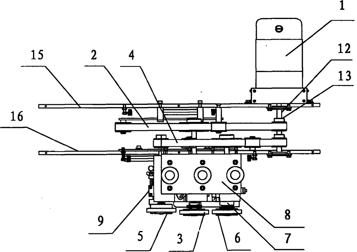
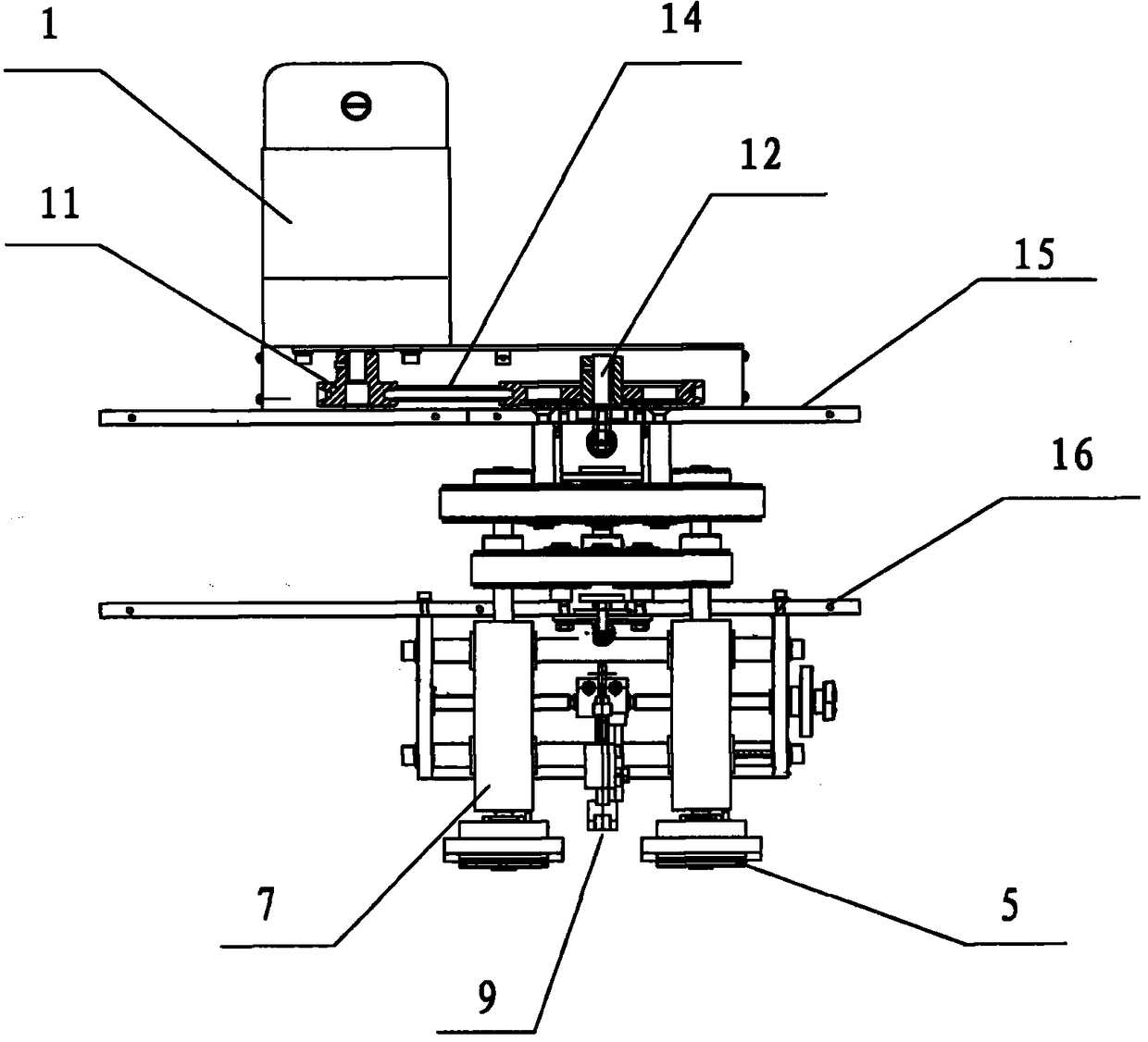
[0018] according to Figure 1~2 The specific structure of the present invention will be described in detail. The capping machine with a synchronous tensioning mechanism includes a motor 1, two sets of transmission parts, and a capping disc; the upper transmission part fixed on the upper mounting plate 15 includes an upper timing belt 2, a pair of second group of timing belt tensioning wheels 3. The shaft of the second group of synchronous belt tensioner 3 is fixed with the second group of capping disc assembly, and the upper synchronous belt 2 is set on the synchronous pulley 13 synchronously driven by the motor 1; the lower one fixed on the lower mounting plate 16 The transmission components include the lower synchronous belt 4, a pair of the first synchronous belt tensioner 5, a third synchronous belt tensioner 6; the first synchronous belt tensioner 5 and the third synchronous belt tensioner The first set of capping disc assemblies and the third set of capping disc assembl...


PUM


Abstract

The invention provides a capping machine with a synchronous tensioning mechanism and solves the problems that product quality is affected by different operation technical levels, the placing of bottlecaps at different heights and non-flush cap bodies after capping in the prior art. The capping machine comprises a motor, two groups of transmission components and cap screwing discs, wherein an upper synchronous belt and the second group of synchronous belt tensioning wheels are fixedly arranged on an upper mounting plate, the second group of cap screwing disc assemblies are fixedly arranged onshafts of the second group of synchronous belt tensioning wheels, and the upper synchronous belt is arranged on the synchronous belt wheels synchronously driven by the motor in a sleeving manner; a lower synchronous belt, the first group of synchronous belt tensioning wheels and the third group of synchronous belt tensioning wheels are fixedly arranged on a lower mounting plate; and a hollow shaftis sequentially connected with a fixing sleeve arranged on an end surface cam in a sleeving manner, lower trays, bottle driving discs, eccentric trays and upper trays from the bottom to the top, theupper trays are connected with a planetary gear through a planetary gear shaft, and the planetary gear is meshed with a central gear. The capping machine is reasonable in design, compact in structureand reasonable in space occupation. The cap screwing mechanism is stable and locks the caps in place, so that the qualified rate of the products is high.

Description

technical field [0001] The invention belongs to the technical field of packaging machinery, and in particular relates to a cap locking machine with a synchronous tensioning mechanism capable of realizing automatic cap locking, low work intensity of operators and high production efficiency. Background technique [0002] At present, in the traditional bottling and packaging process, the locking of the cap after bottling is realized by manual capping and manual locking. Therefore, in the traditional bottle packaging, the manual operation content is large and the labor intensity is high. It is precisely because of this low level of automation and manual operation that the production efficiency of the enterprise is low, and the output cannot be improved in a breakthrough. In addition, due to the manual operation and uneven technical level, there are differences in the height of the bottle cap placement, which makes the cap body uneven after locking the cap, which affects the qual...

Claims


Application Information

Patent Timeline
Patent Type & Authority Applications(China)
IPC IPC(8): B67B3/12F16H7/08
CPCB67B3/12F16H7/08F16H2007/0802
Inventor 许森林
Owner 沈阳星辉利包装机械有限公司
Why Eureka
Try Eureka