
A high-pressure explosion-proof gear pump housing

A gear pump, explosion-proof type technology, applied in the direction of pumps, pump components, rotary piston pumps, etc., can solve the problems of inconvenient connection of booster gear pumps, unclean flow channel cleaning, increased fluid temperature rise, etc., to avoid Fluid energy loss and flow pulsation, simple structure, and the effect of reducing fluid temperature rise

Active Publication Date: 2021-12-21
GUIZHOU HONGLIN MACHINERY
View PDF5 Cites 0 Cited by
  • Summary
  • Abstract
  • Description
  • Claims
  • Application Information

AI Technical Summary

Problems solved by technology

[0003] 1) Stress concentration at the joints between the flow channels and low structural strength
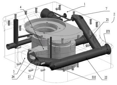
[0004] 2) Each flow channel is in a straight pipe structure, and the flow channels are mainly connected by crossing right angles or oblique angles. In addition, a blind hole 222 is also produced; the C and D flow passages turn to the connection, and the cover plate is required to block the processing holes of the two flow passages, which is difficult to seal and the sealing effect is not good.
[0005] 3) The oil passage inlet of the A flow channel (that is, the outlet of the booster gear pump) is arranged obliquely, which is inconvenient to connect with the booster gear pump, and it is difficult to seal after the connection
[0006] 4) Since the connection structure between the flow channels is a cross right angle or oblique connection, there will inevitably be cecum or dead holes between the flow channels, which will easily cause the flow channels to be unclean; in addition, the cecum or dead holes will also cause fluid circulation in the flow channels Unsmooth, forming eddy current, causing local fluid energy loss and flow pulsation, increasing fluid temperature rise

Method used


Image

  • A high-pressure explosion-proof gear pump housing
  • A high-pressure explosion-proof gear pump housing
  • A high-pressure explosion-proof gear pump housing

Examples


Embodiment Construction

[0029] The present invention will be described in further detail below in conjunction with the accompanying drawings and embodiments, but not as a basis for limiting the present invention.

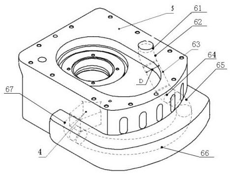
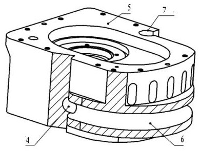
[0030] Example. A high-pressure explosion-proof gear pump housing, constituted as follows Figure 2-6 The housing main body 5 shown is included, and the oil passage 6 is arranged inside the housing main body 5; the oil passage 6 includes a No. 1 flow passage 61, and one end of the No. 1 flow passage 61 is provided with an oil passage inlet 7, The other end is connected with the second flow channel 63 through the first transition flow channel 62, the second flow channel 63 is connected with the third flow channel 66 through the second transition flow channel 64 and the third transition flow channel 65, and the third flow channel 66 is connected with the third flow channel 66. The fourth transition channel 67 is connected, and the fourth transition channel 67 is connected to the inlet 4 of ...


PUM


Abstract

The invention discloses a high-pressure explosion-proof gear pump casing. Including the housing main body (5), the housing main body (5) is provided with an oil channel (6); the oil channel (6) includes a No. 1 flow channel (61), a No. 1 flow channel (61 ) is provided with an oil passage inlet (7), the other end is connected to the No. 2 flow channel (63) through the first transition flow channel (62), and the No. 2 flow channel (63) is connected to the The third transition flow channel (65) is connected to the third flow channel (66), and the third flow channel (66) is connected to the high-pressure gear pump inlet (4) through the fourth transition flow channel (67); the oil passage inlet (7) Connect with booster gear pump. The invention has the characteristics of high structural strength, simple structure, convenient connection, low sealing difficulty, good sealing effect, easy cleaning, smooth fluid circulation, small fluid energy loss and small fluid temperature rise.

Description

technical field [0001] The invention relates to the field of gear pumps, in particular to a high-pressure explosion-proof gear pump housing. Background technique [0002] The traditional high-pressure explosion-proof gear pump casing has a structure such as figure 1 As shown, in the casing 1, the oil passage inlet 7 (that is, the outlet of the booster gear pump) and the inlet 4 of the high-pressure gear pump are connected through the oil passage 2. The oil passage 2 includes the A flow passage 21, and one end of the A flow passage 21 is connected to the The inlet 7 of the oil passage is connected with the inlet 4 of the high-pressure gear pump through the B flow passage 22, the C flow passage 23 and the D flow passage 24 in turn, and the A flow passage 21 to the B flow passage 22 are connected through a 90° turn, and the B flow passage 22 produces a processing hole, that is, the screw plugging hole 221 needs to be blocked by a screw plug; the B flow channel 22 to the C flow...

Claims


Application Information

Patent Timeline
Patent Type & Authority Patents(China)
IPC IPC(8): F04C15/06F04C15/00F04C2/08
CPCF04C2/08F04C15/00F04C15/06
Inventor 刘荣萍杨杰瞿祖勇刘安用
Owner GUIZHOU HONGLIN MACHINERY
Learn More