Plug valve assembly of embedded gas stove

A technology for cock valves and gas stoves, applied in the direction of cocks including cut-off devices, valve details, valve devices, etc., can solve problems such as corrosion and rust, and achieve the effects of saving production costs, avoiding safety accidents, and preventing rust

Pending Publication Date: 2018-05-29
浙江博顿燃具科技有限公司
View PDF0 Cites 0 Cited by
  • Summary
  • Abstract
  • Description
  • Claims
  • Application Information

AI Technical Summary

Problems solved by technology

Because the built-in gas stove is beautiful, space-saving, and easy to clean, it makes the kitchen more harmonious and complete, and it is more convenient to match with other products. Therefore, it has received the love of consumers, and many families choose it when decorating new houses. For this type of gas cooker, the cock valve assembly is an important accessory of the embedded gas cooker. In the prior art, the structure of the cock valve assembly of the gas cooker is generally like this, as figure 1 As shown, the plug valve assembly consists of a bottom cover 01, a valve body 02, a bottom cover sealing ring 03 arranged between the bottom cover 01 and the valve body 02, a valve core installed on the valve body 02, and a thermoelectric valve installed on the valve body 02. Potential electromagnetic valve, bottom plate 04, knob rod 05 and bracket 06. In this structure, the knob rod 05 passes through the hole on the bracket 06. The knob rod 05 is a columnar rod with milling edge 07. The edge is mainly to drive t

Method used


Image

  • Plug valve assembly of embedded gas stove
  • Plug valve assembly of embedded gas stove
  • Plug valve assembly of embedded gas stove

Examples


Embodiment Construction

[0014] The invention will be further described below with reference to the accompanying drawings and in combination with specific embodiments, so that those skilled in the art can implement it by referring to the description, and the protection scope of the present invention is not limited to the specific embodiments.

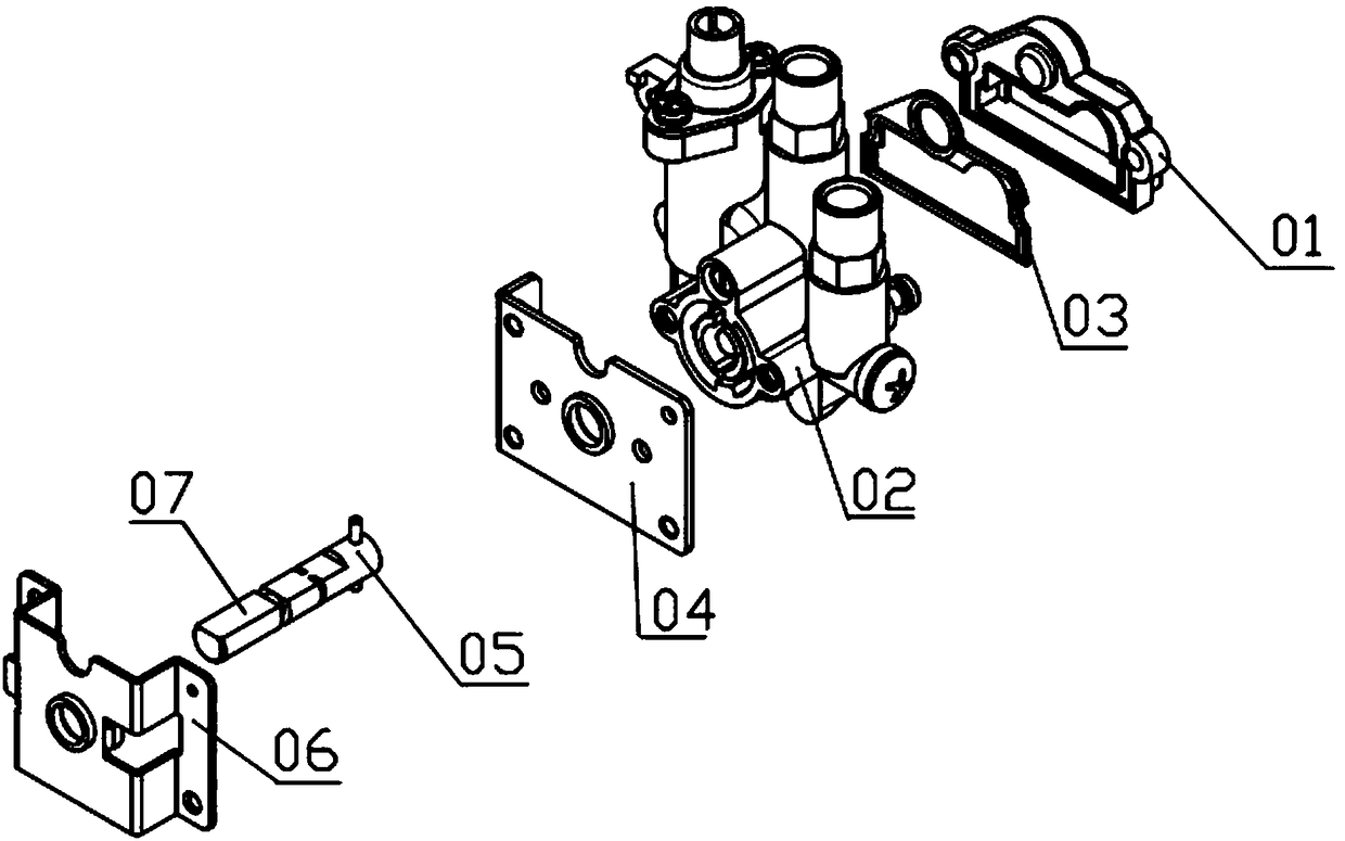
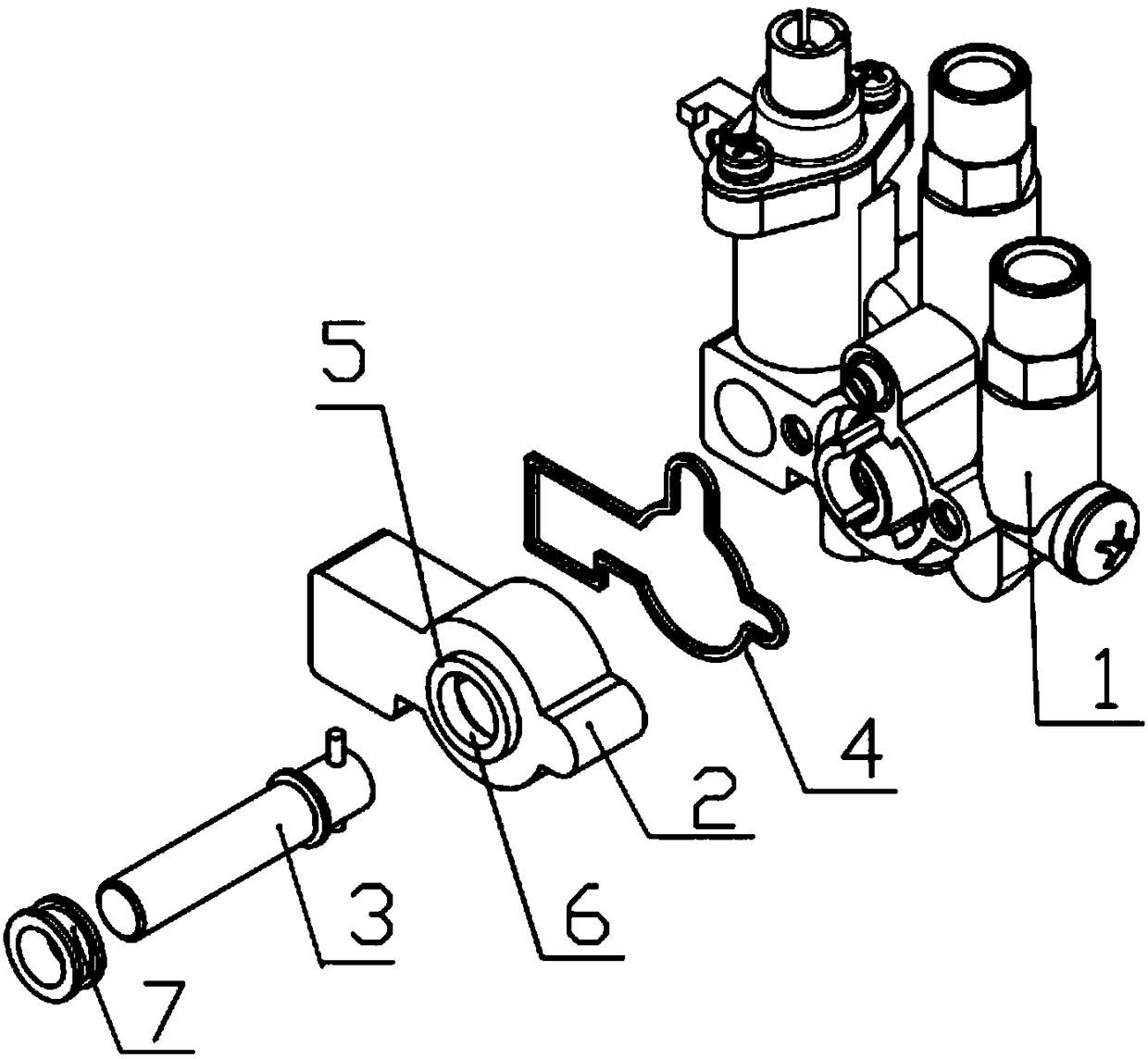
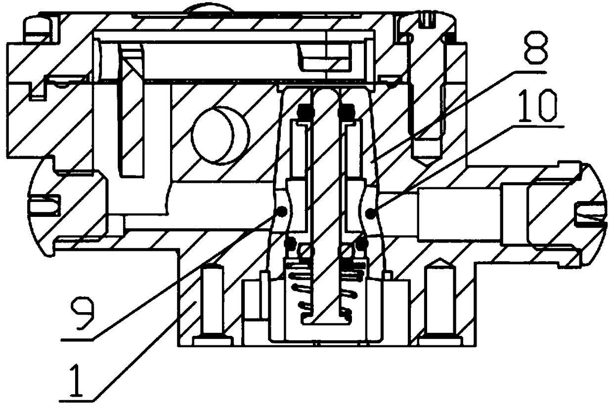
[0015] The invention relates to a plug valve assembly of an embedded gas cooker, such as figure 2 As shown, it includes a valve body 1, a valve cover 2 covered on the valve body 1, a cylindrical knob rod 3, and a seal 4 arranged between the valve cover 2 and the valve body 1, and the seal 4 is embedded in the valve body. On the inner side wall of the cover 2 , the valve cover 2 is provided with a through hole 5 through which the knob rod 3 passes, and the through hole 4 includes a fitting ring surface 6 formed between the knob rod 3 . With this structure, the knob rod 07 with milling edge 09 is replaced with a pure cylindrical knob rod 3. On this basis, the br...


PUM


Abstract

The invention relates to a plug valve assembly of an embedded gas stove. The valve assembly comprises a valve body, a valve cover, a cylindrical knob rod and a sealing element, wherein the valve covercovers the valve body, and the sealing element is arranged between the valve cover and the valve body; the sealing element is inlaid in the inner side wall of the valve cover; and a through hole allowing the knob rod to penetrate through is formed in the valve cover, and the through hole comprises a fitting ring surface formed between the through hole and the knob rod. According to the plug valveassembly, a knob rod with a cross section is replaced with the pure cylindrical knob rod, the cylindrical knob rod penetrates through the valve cover to enter the valve body, the contact position between the knob rod and the valve cover is in a completely attached state, so that the fitting ring surface is formed, an open type contact mode is avoided, and therefore liquid can be prevented from entering the interior of the plug valve from the knob rod, and internal parts are prevented from being rusted; and according to the plug valve of the embedded gas stove, a bottom cover and a bottom cover sealing ring in the prior art are eliminated, so that the phenomenon of water accumulation at the bottom cover in the prior art is avoided, the situation that rusting is caused due to the fact thatthe internal parts are corroded by accumulated water is avoided, and meanwhile, production cost is also saved.

Description

technical field [0001] The invention relates to the technical field of gas cooker accessories, in particular to a plug valve assembly of an embedded gas cooker. Background technique [0002] The gas stove usually controls the opening and closing of the gas stove through the cock valve. At present, the embedded gas stove is used more. The stove cabinet of the stove is in a plane with the countertop of the cabinet. Because the built-in gas stove is beautiful, space-saving, and easy to clean, it makes the kitchen more harmonious and complete, and it is more convenient to match with other products. Therefore, it has received the love of consumers, and many families choose it when decorating new houses. For this type of gas cooker, the cock valve assembly is an important accessory of the embedded gas cooker. In the prior art, the structure of the cock valve assembly of the gas cooker is generally like this, as figure 1 As shown, the plug valve assembly consists of a bottom cove...

Claims


Application Information

Patent Timeline
IPC IPC(8): F16K5/02F16K5/08F16K27/12
CPCF16K5/0257F16K5/08F16K27/12
Inventor 徐宏远刘雁云
Owner 浙江博顿燃具科技有限公司
Why Eureka
Try Eureka