
Lamp bulb shell

A technology of lamps and bulbs, which is applied to the damage prevention measures of lighting devices, lighting and heating equipment, light sources, etc. It can solve the problems of only reaching 250 degrees, only 270 degrees, and the loss of effective lumens of the whole lamp. Achieve the effects of reduced loss, soft and uniform light, and improved light transmission

Inactive Publication Date: 2018-05-29
MAINHOUSE (XIAMEN) ELECTRONICS CO LTD
View PDF4 Cites 0 Cited by
  • Summary
  • Abstract
  • Description
  • Claims
  • Application Information

AI Technical Summary

Problems solved by technology

[0005] Since the heat dissipation of the LED chip is a problem that determines the luminous efficiency and lifespan, in order to ensure good heat dissipation, the above-mentioned LED lamp with a double-layer bulb needs to be provided with a larger volume to ensure the heat dissipation efficiency of the LED. Therefore, the above-mentioned double-layer bulb The lamp body of the bulb LED lamp is relatively thick, and there is still a big difference in appearance from the traditional incandescent bulb lamp
Secondly, the LED chip of the above-mentioned LED lamp with double-layer bulbs gradually diffuses through the two layers of milky white bulbs, the effective lumens of the whole lamp will be seriously lost, and the diffusion angle can only reach about 250 degrees. Even if the reflector cup is added, its The light angle can only reach about 270 degrees

Method used


Image

  • Lamp bulb shell
  • Lamp bulb shell
  • Lamp bulb shell

Examples


Embodiment Construction

[0039] In order to further explain the technical solutions of the present invention, the present invention will be described in detail below through specific embodiments.

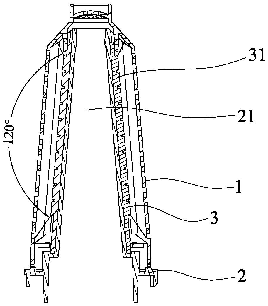
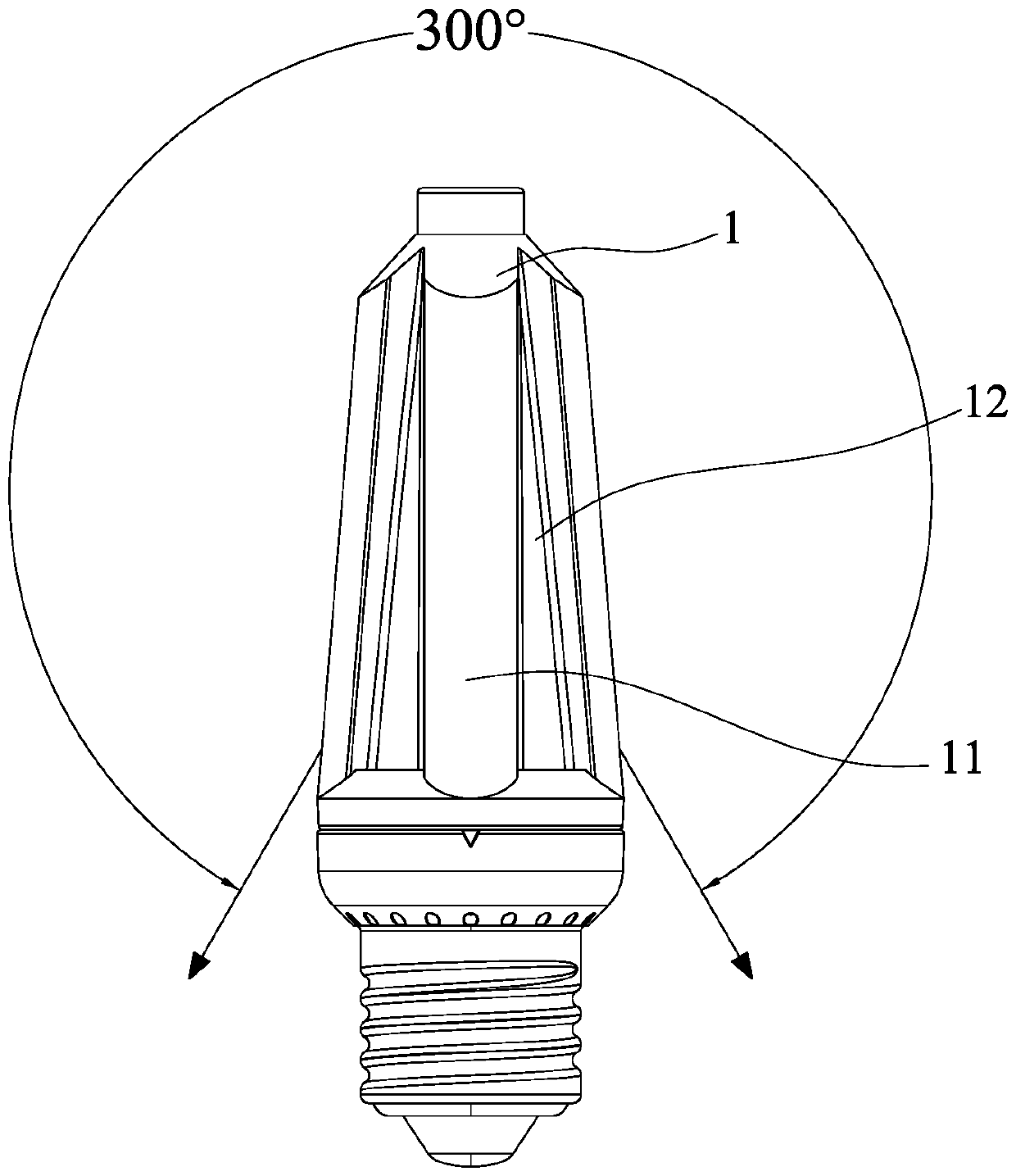
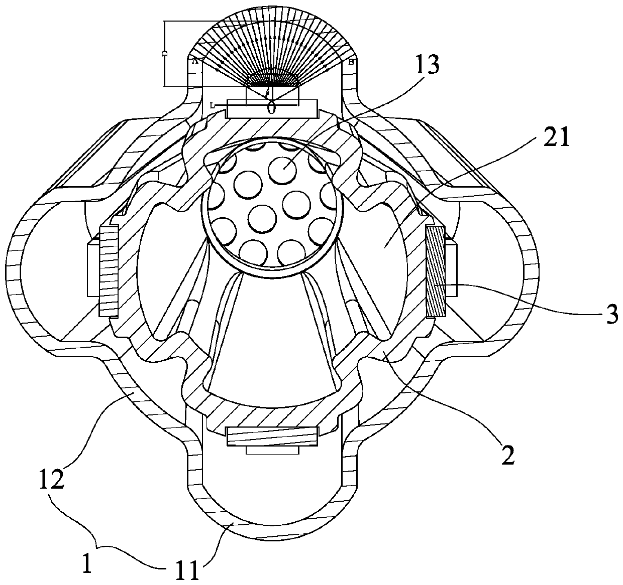
[0040] like figure 1 and figure 2 As shown, the present invention discloses a lamp bulb, which is sleeved on the outer periphery of a columnar base 2. The lamp bulb is a hollow columnar shell 1 designed corresponding to the columnar base, and the outer ring of the columnar base 2 At least one LED light bar 3 is provided, and a plurality of LED chips 31 are distributed on the LED light bar 3 , and the distance between the LED chips 31 on each LED light bar 3 and the housing 1 is D>0.

[0041] In various embodiments of the present invention, the columnar base 2 is a heat-dissipating aluminum piece that is wide at the bottom and narrow at the top. In addition, the columnar base 2 can also be set at the same width up and down or narrow at the bottom and wide at the top. . A heat dissipation channel 21 is fo...


PUM


Abstract

The invention discloses a lamp bulb shell. The lamp bulb shell is arranged on the periphery of a columnar base in a coordinating sleeving manner. The lamp bulb shell is a hollow columnar shell which is designed corresponding to the columnar base. The outer ring of the columnar base is provided with at least one LED light bar. A plurality of LED chips are distributed on the LED light bars, and thedistance D between each LED chip on each LED lamp bar and the shell is larger than 0. According to the lamp bulb shell, due to the fact that the periphery of the columnar base is provided with the LEDlamp bar, the light emitting area can be greatly increased, by coordinating with the shell covering the LED light bars and playing a role in light uniformizing and dazzling preventing, after light rays of the LED chips are diffused by the shell, the light emitting angle of a whole lamp is larger than 300 degrees, and compared with an existing LED lamp with a double-layer bulb shell, the whole lamp is wider in light emitting range; and the columnar base is longitudinally arranged, the LED light bars are distributed in the double-layer bulb shell in a three-dimensional manner, a heavy lamp holder cannot appear in the bulb lamp which is formed in this way, and therefore the bulb lamp is more approximate to a traditional incandescent light bulb in appearance.

Description

technical field [0001] The invention relates to the technical field of lamps, in particular to a lamp bulb. Background technique [0002] Traditional incandescent lamps have a relatively large luminous angle, but compared with LED lamps, they have high energy consumption and short service life. Now the markets in Europe and the United States are in great need of LED bulb lamps with large angles to replace traditional incandescent lamps. The lights are similar. [0003] LED is made of electroluminescent semiconductor material, which has excellent characteristics such as low voltage, high efficiency, good monochromaticity, strong applicability, good stability, short response time, long life, and no pollution to the environment. Widely used in lighting, decoration and other fields. An LED bulb based on LED chips has emerged as the times require. An important difference between this kind of LED bulb and traditional incandescent bulbs is that the illuminants in the bulb are rep...

Claims


Application Information

Patent Timeline
Patent Type & Authority Applications(China)
IPC IPC(8): F21K9/237F21V29/503F21V29/83F21Y115/10
CPCF21K9/232F21K9/237F21V5/04F21V5/045F21V15/01F21V29/503F21V29/83F21Y2115/10
Inventor 周南庆吴荣奎
Owner MAINHOUSE (XIAMEN) ELECTRONICS CO LTD
Learn More