Method for obtaining three-dimensional coordinates of light bar center based on binocular line structured light in welding detection

A technology of welding detection and three-dimensional coordinates, which is applied in the field of acquisition of three-dimensional coordinates of the light bar center based on binocular line structured light in welding detection, can solve problems that affect visual detection, cannot accurately and effectively obtain three-dimensional size information, and achieve welding vision Detect precise effects

Active Publication Date: 2018-05-29
ZHEJIANG UNIV OF TECH
View PDF13 Cites 23 Cited by
  • Summary
  • Abstract
  • Description
  • Claims
  • Application Information

AI Technical Summary

Problems solved by technology

[0007] In order to overcome the shortcomings of existing robot welding that welding interference affects visual inspection and cannot accurately and effectively obtain three-dimensional size information on the weld surface, the prese

Method used


Image

  • Method for obtaining three-dimensional coordinates of light bar center based on binocular line structured light in welding detection
  • Method for obtaining three-dimensional coordinates of light bar center based on binocular line structured light in welding detection
  • Method for obtaining three-dimensional coordinates of light bar center based on binocular line structured light in welding detection

Examples


Embodiment Construction

[0051]The present invention will be further described below in conjunction with the accompanying drawings.

[0052] refer to Figure 1 to Figure 12 , a method for obtaining three-dimensional coordinates of the light bar center based on binocular line structured light in welding inspection, comprising the following steps:

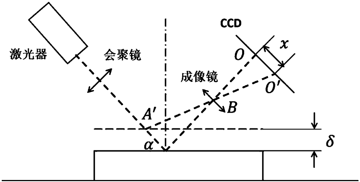
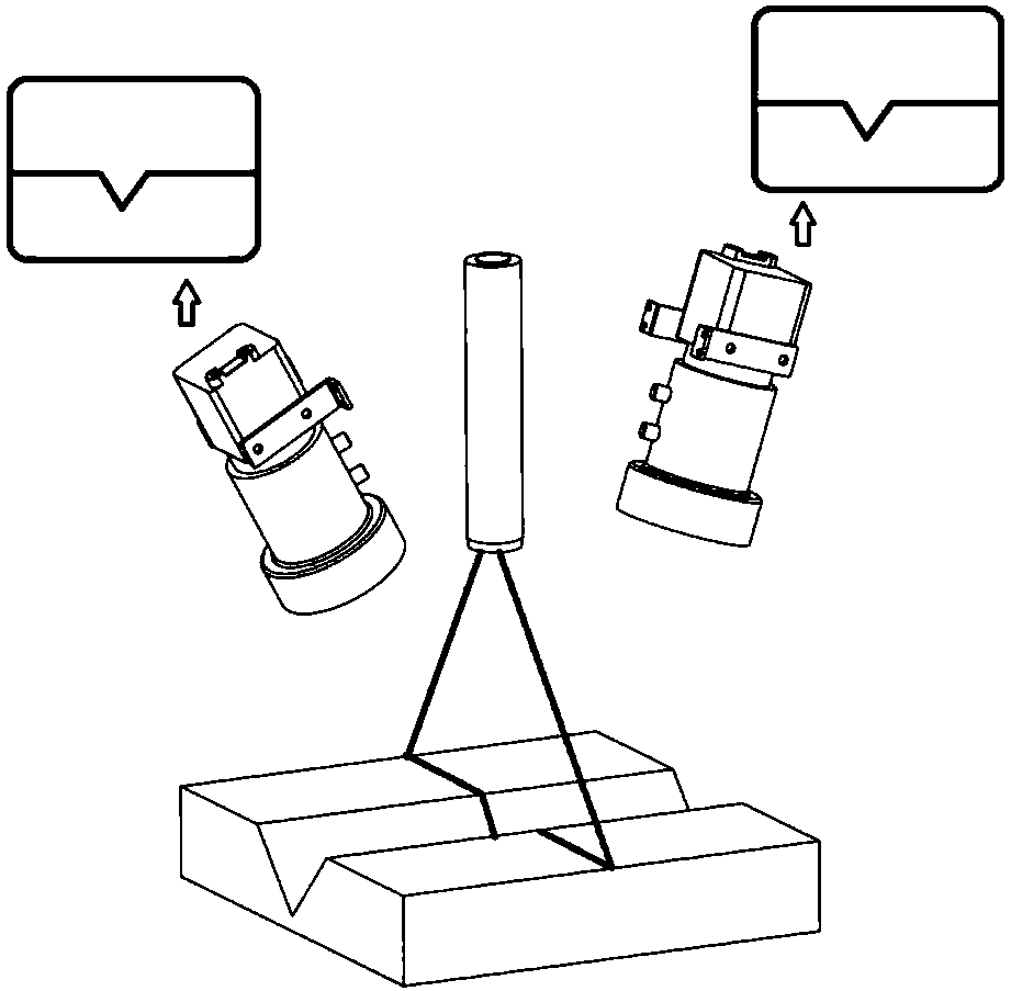
[0053] 1) Build a binocular structured light vision sensing system and install it at the end of the robot. The solution can adopt the conventional binocular line structured light solution, such as figure 2 As shown, a narrow-band filter with the same wavelength range as the line-structured light is installed on the camera to filter out light other than the wavelength of the structured light.

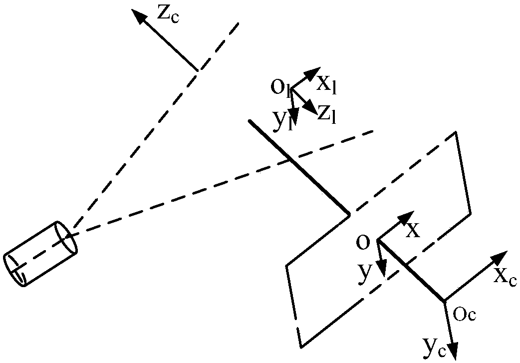
[0054] 2) Calibrate the binocular structured light vision sensing system, including the calibration of two cameras, the calibration of the light plane, and the calibration of the hand-eye.

[0055] 3) Use the calibrated binocular line structured light device to sim...


PUM


Abstract

The invention provides a method for obtaining three-dimensional coordinates of a light bar center based on binocular line structured light in welding detection. The method comprises the steps of (1) building a binocular line structured light visual sensing system, (2) calibrating the binocular line structured light visual sensing system, (3) obtaining images with structural light stripes at the same time during welding by using calibrated binocular line structured light device, (4) mapping pixel coordinates of pixels with non-zero grayscale values in two images to a plane in a three-dimensional space and selecting a light plane or an imaging plane of one camera, (5) judging whether a point is a noise point or a point in a light strip through three-dimensional coordinate points of the pixels in the two images in the same plane in a space coordinate system, and (6) obtaining a pose relationship between a camera and a robot end by hand-eye calibration, and mapping the coordinate valuesof a center line on the light plane to a robot coordinate system to obtain the surface shape of a weld seam in robot coordinates. According to the method, the visual inspection of welding is more accurate.

Description

technical field [0001] The invention relates to a method for extracting the three-dimensional coordinates of the light bar center based on the binocular line structured light in the real-time detection of robot automatic welding, especially for the extraction of the three-dimensional coordinates of the center line of the line structured light under the interference of arc light, spatter and reflection during welding. Background technique [0002] Welding is an important material forming and processing technology in the field of contemporary manufacturing, and it has been widely used in industrial manufacturing fields such as construction engineering, aerospace, machinery manufacturing, and electronics. The development of welding and related industries is of great significance to my country's transformation from a manufacturing power to a manufacturing power. In welding, the shortcomings of manual welding are mainly manifested in the high labor intensity of welders, and the s...

Claims


Application Information

Patent Timeline
IPC IPC(8): G01B11/25
CPCG01B11/254
Inventor 鲍官军庞加庆黄锦成李玉蔡世波杨庆华胥芳
Owner ZHEJIANG UNIV OF TECH
Why Eureka
Try Eureka