Super-large depth-of-field imaging system based on wavefront coding
A wavefront coding and imaging system technology, applied in the optical field, can solve problems such as increasing the difficulty of optical system design and optimization, and achieve the effect of clear imaging
- Summary
- Abstract
- Description
- Claims
- Application Information
AI Technical Summary
Problems solved by technology
Method used
Image

Examples
Embodiment Construction
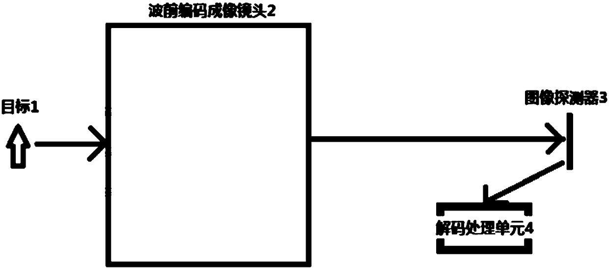
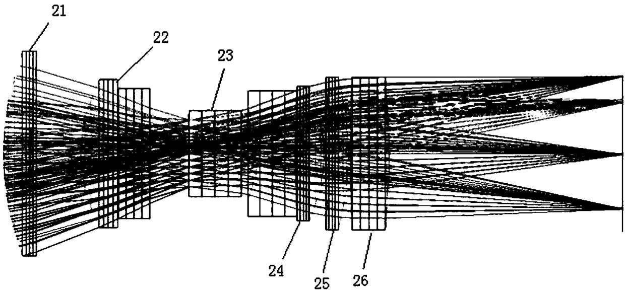
[0040] see figure 1 as well as figure 2 , the present invention provides an imaging system based on wavefront coding with super large depth of field, which can realize large relative aperture, super large depth of field and large field of view at the same time, including wavefront coding imaging lens, 1 / 1.8 inch image detector and decoding processing unit , the wavefront encoding imaging lens includes a first lens 21, a second lens 22, a phase mask plate 23, a third lens 24, a fourth lens 25 and a fifth lens 26; the first lens 21, the second lens 22, the phase mask Diaphragm 23, third lens 24, fourth lens 25, fifth lens 26, and 1 / 1.8-inch image detector are sequentially arranged on the same optical path; the wavefront encoding imaging system adopts an asymmetrical double Gaussian structure with a circular aperture , wherein the radius of curvature of the front and rear surfaces of the first lens 21 and the radius of curvature of the front and rear surfaces of the fourth lens...
PUM
| Property | Measurement | Unit |
|---|---|---|
| Surface radius of curvature | aaaaa | aaaaa |
| Focal length | aaaaa | aaaaa |
| Full field of view | aaaaa | aaaaa |
Abstract
Description
Claims
Application Information
 - Generate Ideas
- Intellectual Property
- Life Sciences
- Materials
- Tech Scout
- Unparalleled Data Quality
- Higher Quality Content
- 60% Fewer Hallucinations
Browse by: Latest US Patents, China's latest patents, Technical Efficacy Thesaurus, Application Domain, Technology Topic, Popular Technical Reports.
© 2025 PatSnap. All rights reserved.Legal|Privacy policy|Modern Slavery Act Transparency Statement|Sitemap|About US| Contact US: help@patsnap.com