
Magnetron

A technology of magnetron and circular tube, applied in the field of magnetron, can solve the problems of insufficient heat dissipation of sleeve, complicated processing of heat dissipation components, loss of heat dissipation effect of heat dissipation plate, etc.

Active Publication Date: 2018-05-29
GUANGDONG WITOL VACUUM ELECTRONICS MFR
View PDF5 Cites 3 Cited by
  • Summary
  • Abstract
  • Description
  • Claims
  • Application Information

AI Technical Summary

Problems solved by technology

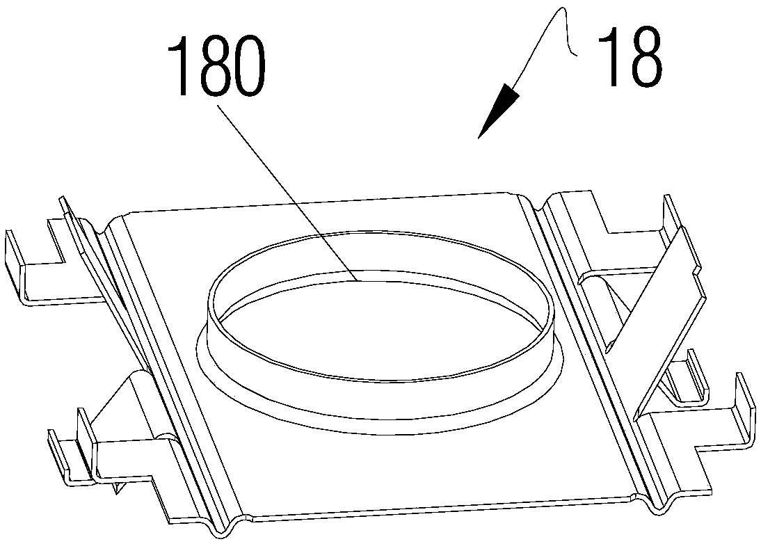
[0007] The above scheme can simplify the assembly steps between the heat dissipation component and the black ball component during assembly, but the processing of the heat dissipation component itself becomes more complicated, and more importantly, the sleeve needs to pass through each layer of heat dissipation plate and connect with the heat dissipation Each anode hole on the plate is in close contact with
If the anode hole is processed before the metal plate is bent, the coaxiality of the anode hole on the multi-layer heat sink is limited by the bending process and the error of punching, and these differences may cause the sleeve and the heat sink Poor contact leads to insufficient heat dissipation on the sleeve; if the anode hole is processed after the metal plate is bent, the process of opening the anode hole itself will change the size of the gap between the cooling plates along the axis of the sleeve (The force direction of the punching is the axial direction of the sleeve, which will inevitably cause the metal plate to deform in this direction), and the gap between adjacent cooling plates is the air duct for heat exchange, so this method will also The gap between the affected parts of the heat sink is too small and the heat dissipation effect is lost

Method used


Image

  • Magnetron
  • Magnetron
  • Magnetron

Examples


Embodiment Construction

[0035] In the present invention, unless stated to the contrary, the used orientation words such as "up, down, left, right" usually refer to the directions shown in the drawings or to the vertical, vertical or neutral directions. Words are used to describe the mutual positional relationship of each component upwardly. "Inside and outside" means that relative to the shell of the part, the space covered by the shell is "inside", and the outside of the shell is "outside".

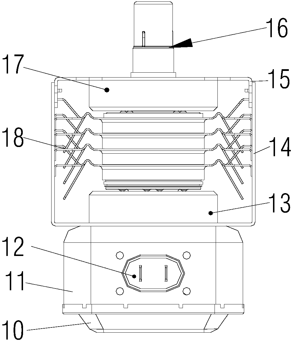
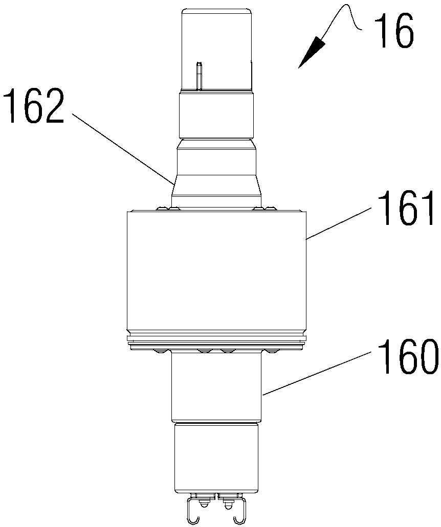
[0036] In order to facilitate the understanding of the cooperation relationship between the magnetron cooling element and other parts, a typical related structure of the black ball assembly 16 in the magnetron is firstly introduced here for the convenience of subsequent description. refer to figure 2 As shown, the interior of the anode cylinder 161 in the black ball assembly 16 is a resonant cavity, and electrons complete energy conversion in this space. Therefore, the heat in the magnetron is mainly generat...


PUM


Abstract

The invention, which relates to the field of magnetron structure, discloses a magnetron comprising a magnetron heat-dissipating element for dissipating heat from the magnetron. The magnetron heat-dissipating element consists of a central heat-conducting body (1) coating and being in contact with the outer side wall of an anode cylinder (161), a heat transferring plate (2) extending externally fromthe central heat-conducting body (1), and a plurality of cooling fin groups that are arranged on at least one plane of the heat transferring plate (2) vertically and are spaced at intervals. A direct-current air duct is formed corresponding between each two adjacent cooling fin groups. According to the magnetron, while the structure of the magnetron heat-dissipating element and the mounting structures of the magnetron heat-dissipating element and a black ball assembly are simplified to a certain extent, the heat transfer efficiency between the anode cylinder and the magnetron heat-dissipatingelement and inside the magnetron heat-dissipating element are improved, so that the heat radiation efficiency of the magnetron is enhanced.

Description

technical field [0001] The invention relates to the technical field of magnetron structures, in particular to a magnetron. Background technique [0002] Magnetron is a kind of microwave electron tube, which is a reentrant resonant cross-field oscillator, usually used as a high-power microwave generator. Due to the working characteristics of the magnetron itself, even under normal working conditions, the resonant cavity of the magnetron generates a large amount of heat. Therefore, proper cooling is an important condition to ensure the normal operation of the magnetron. When a high-power magnetron is used, its anode needs to be water-cooled to achieve the purpose of temperature control. [0003] For the magnetron used for heating in microwave ovens, because of its low power, forced air cooling is often used for cooling. Specifically, see figure 1 The magnetron structure shown shows the composition and assembly structure of the magnetron in the prior art. In this magnetron ...

Claims


Application Information

Patent Timeline
IPC IPC(8): H01J23/00H01J25/50
CPCH01J23/005H01J25/50
Inventor 陈文
Owner GUANGDONG WITOL VACUUM ELECTRONICS MFR
Learn More