
A capacitor-type hybrid DC circuit breaker for DC power grid and its control method

A hybrid DC and DC power grid technology, applied in emergency protection circuit devices, circuit devices, emergency protection circuit devices for limiting overcurrent/overvoltage, etc., can solve problems such as large on-state loss, avoid collapse, reduce Small on-state loss, the effect of reducing device usage

Active Publication Date: 2020-02-18
SOUTHEAST UNIV
View PDF2 Cites 0 Cited by
  • Summary
  • Abstract
  • Description
  • Claims
  • Application Information

AI Technical Summary

Problems solved by technology

Solid-state DC circuit breaker is a DC protection technology that mainly uses high-power power electronic devices. Compared with mechanical circuit breakers, it has the advantages of fast switching speed, short-circuit current suppression, and high reliability, but the on-state loss is relatively large.

Method used


Image

  • A capacitor-type hybrid DC circuit breaker for DC power grid and its control method
  • A capacitor-type hybrid DC circuit breaker for DC power grid and its control method
  • A capacitor-type hybrid DC circuit breaker for DC power grid and its control method

Examples


Embodiment 1

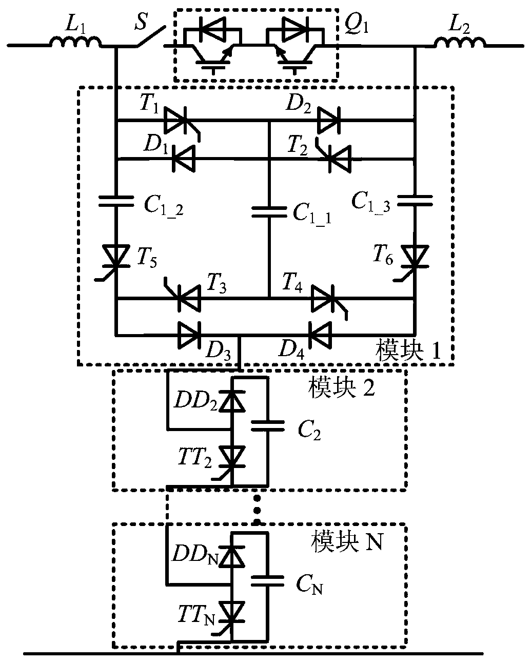
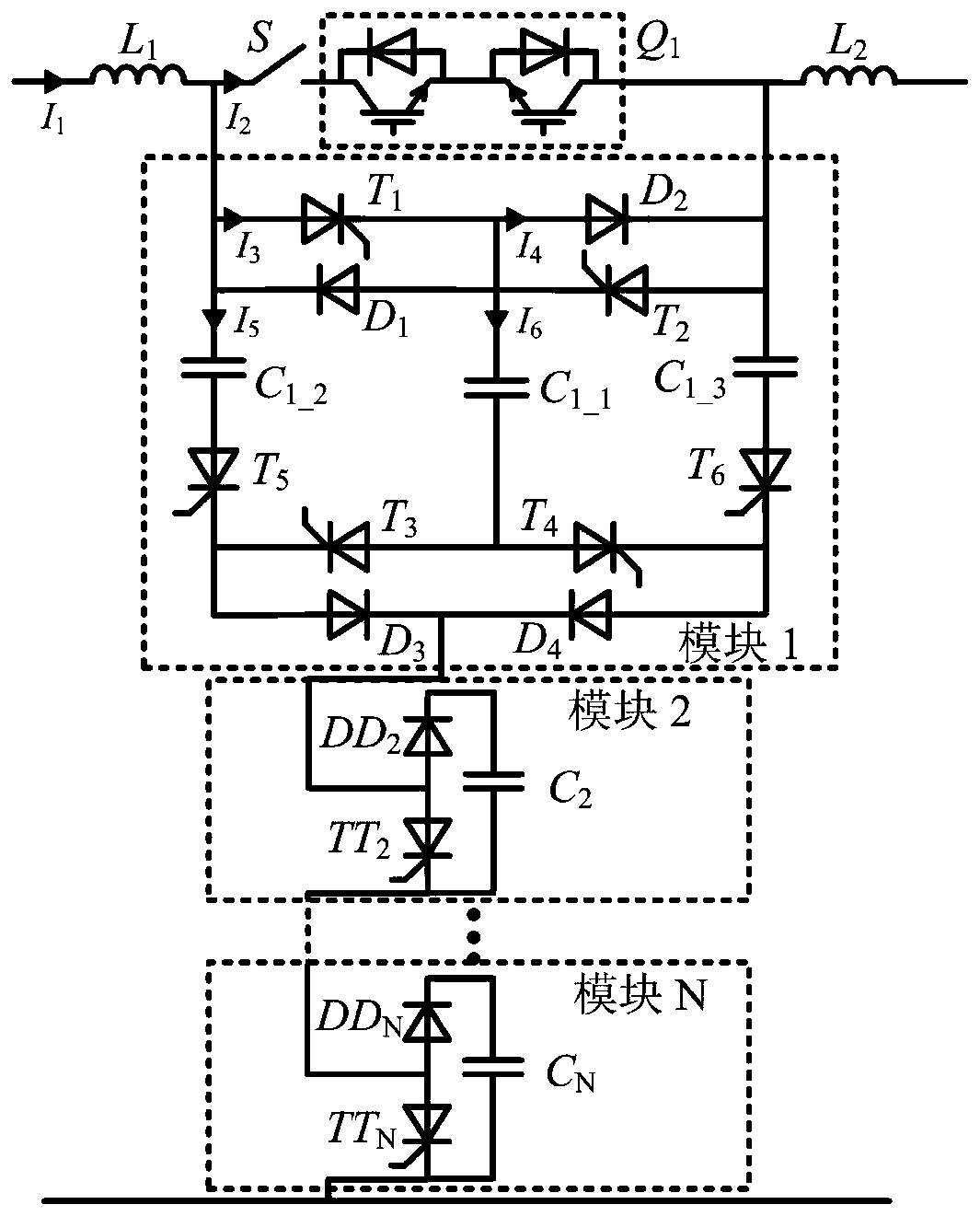
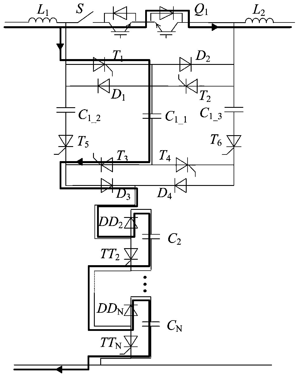
[0036] Such as figure 1 As shown, this embodiment is a capacitive hybrid DC circuit breaker, which is connected between the two poles of the DC power grid, and includes a mechanical switch S, and a switching tube composed of two series-connected IGBTs and their anti-parallel diodes connected in series with the mechanical switch S Group Q 1 , and the modules 1 to N connected in parallel with the series branches, and the modules 1 to N connected in series. The mechanical switch S and two series-connected IGBTs and their antiparallel diodes form a current-carrying branch, which is the current channel of the DC grid under normal conditions. In order to slow down the rising rate of the short-circuit current, the first current-limiting inductor L is usually connected in series on both sides of the circuit breaker. 1 and a second current limiting inductor L 2 .

[0037] Where module 1 includes: three capacitors eleventh capacitor C 1_1 , the twelfth capacitance C 1_2 and the th...

Embodiment 2

[0050] Such as Figure 10 As shown, in this embodiment, a group of resistors and switches connected in series with each other are connected in parallel to each capacitor of all modules. For example, the eleventh capacitor C in module 1 1_1 The eleventh resistance R connected in series with each other is connected in parallel 1_1 and the eleventh switch S 1_1 . The second capacitor C in module 1 3 The second resistance R connected in parallel with each other in series 2 and the second switch S 2 .

[0051] The added resistance and switch form a discharge circuit, which can effectively release the capacitor voltage of the sub-module after the fault is removed, realize the repeated use of the circuit breaker, and ensure the reliability of the hybrid DC circuit breaker.

[0052] Other parts of this embodiment are the same as Embodiment 1.


PUM


Abstract

The invention discloses a capacitance type mixing DC breaker for DC power grid and a control method thereof. The breaker topology comprises one mechanical switch, two IGBTs and anti-parallel diodes thereof, two current-limiting inductance and N sub-modules, wherein a first sub-module comprises three capacitance, six thyristors and four diodes; the left (N-1) sub-modules are of the same; each module comprises one capacitance, one thyristor and one diode. The mechanical switch and two IGBTs and the anti-parallel diodes form a current-carrying branch circuit, which is a normal work channel. N sub-modules form a fault current transferring branch circuit, which provides a fault current transferring channel during short circuit. Under normal condition, the system delivers power through the current-carrying branch, and pre-charging is conducted on each sub-module through the control switch. Once faults occur, the breaker can transfer the fault current through the transferring branch circuit,and thereby the zero-voltage turning-off of the mechanical switch can be realized, and at the same time the pre-charging voltage of the capacitance can effectively limit the short circuit current.

Description

technical field [0001] The invention relates to a capacitive hybrid DC circuit breaker and a control method thereof, which belong to the technical field of power electronics and are mainly used in multi-terminal DC transmission occasions. Background technique [0002] The continuous consumption of traditional energy and the increasingly serious environmental problems make the development and application of clean and sustainable energy gradually attract the attention of countries all over the world. The consumption capacity of the traditional power grid has certain limitations, and the power generation of new energy is intermittent and uncertain, so that the utilization efficiency of new energy is not high. Multi-terminal DC transmission and DC grid technology are effective measures to solve the above problems and are an important part of the future development of power systems. [0003] However, due to the low resistance and low inertia of the DC power grid, a small voltage...

Claims


Application Information

Patent Timeline
Patent Type & Authority Patents(China)
IPC IPC(8): H02H9/02H02H3/087
CPCH02H3/087H02H9/02
Inventor 陈武叶晗
Owner SOUTHEAST UNIV
Learn More