Converter control method and controlling device

A control method and technology of a control device are applied in the conversion device of output power, the conversion of AC power input to DC power output, electrical components, etc., which can solve the problems of failure and damage of power semiconductor devices, and avoid excessive voltage stress and increase. The effect of internal temperature

Inactive Publication Date: 2018-05-29
SUNGROW POWER SUPPLY CO LTD
7 Cites 0 Cited by

AI-Extracted Technical Summary

Problems solved by technology

Therefore, when the converter is started under low temperature conditions, the power semiconduc...

Abstract

The invention discloses a converter control method and a controlling device. The converter comprises two converting units having the same topology structures. The direct current sides of the two converting units are connected to the direct current source in parallel, and the AC sides of the two converting units are connected to an alternating current filter in parallel, and the midpoints of the direct current bus of the two converting units are directly connected. The converter also comprises an inductor which is in series connection between the midpoint of at least one converting unit and thealternating current filter. The converter control method comprises the steps that the internal temperature value of the converter can be obtained; whether the internal temperature value of the converter is lower than the first set value can be determined; if the internal temperature value of the converter is lower than the first set value, the on-off state of switch tubes in the two converting units can be controlled. Current can flow out from the anode of the direct current source, and passes through a plurality of switch tubes and inductors in the converter and returns to the cathode. The current value is no more than the limit value, and thereby the power semiconductor device of the converter can be prevented from being failed and damaged due to the fact that the voltage stress is excessively large when the converter is started at low temperature.

Application Domain

Technology Topic

Image

  • Converter control method and controlling device
  • Converter control method and controlling device
  • Converter control method and controlling device

Examples

  • Experimental program(1)

Example Embodiment

[0033] The following will clearly and completely describe the technical solutions in the embodiments of the present invention with reference to the accompanying drawings in the embodiments of the present invention. Obviously, the described embodiments are only some, not all, embodiments of the present invention. Based on the embodiments of the present invention, all other embodiments obtained by persons of ordinary skill in the art without making creative efforts belong to the protection scope of the present invention.
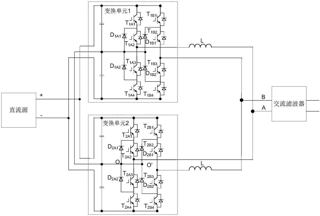
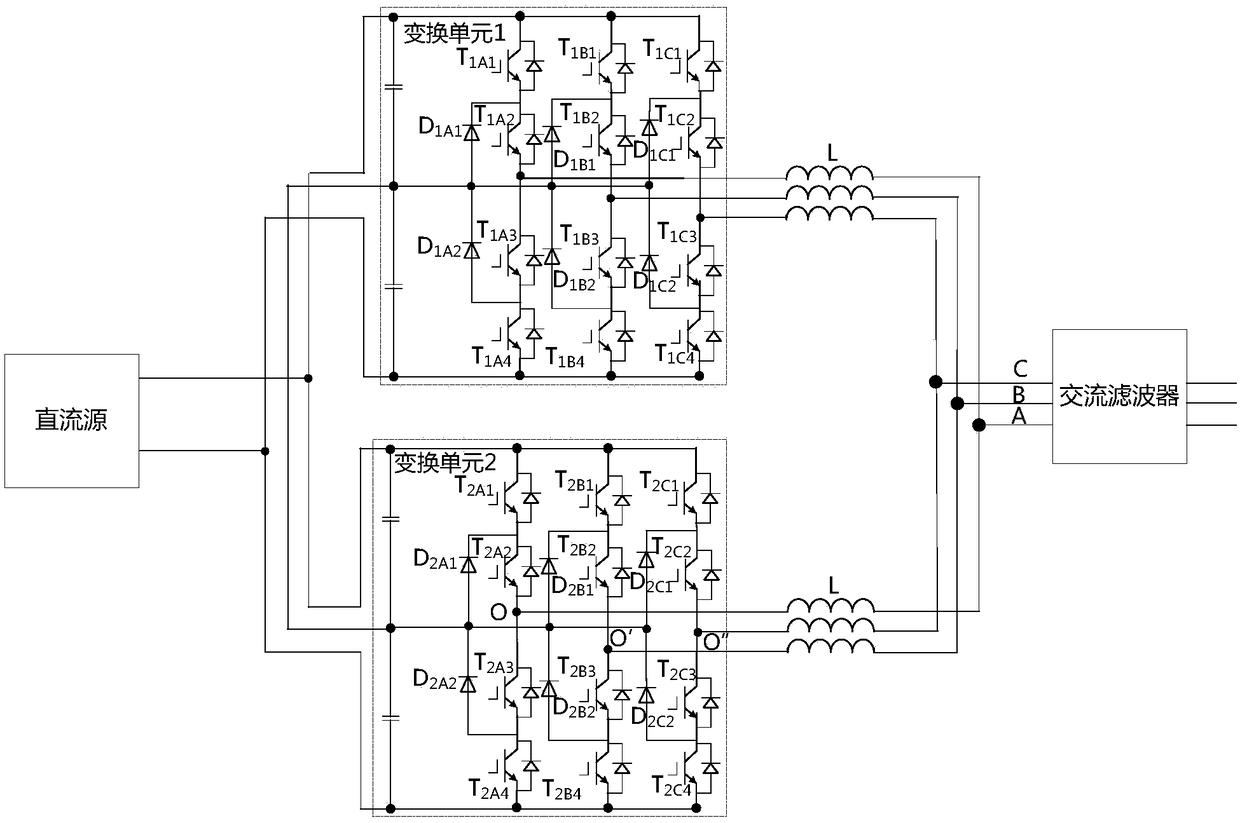
[0034] Both the converter control method and the converter control device disclosed in the embodiments of the present invention are proposed for the converter with the following topology, and the purpose is to prevent the power semiconductor device of the converter from Failure and damage due to excessive voltage stress during start-up, the topology of the converter is specifically described as follows:
[0035] The converter includes two conversion units with the same topology; the DC side of the two conversion units is connected to a DC source (such as a photovoltaic panel or a storage battery) in parallel, and the AC side is connected to an AC filter in parallel, and The DC bus midpoints of the two conversion units are directly connected;
[0036] In addition, the converter further includes an inductor connected in series between the midpoint of the bridge arm of at least one conversion unit and the AC filter.
[0037] The converter can be a single-phase converter, such as using figure 1 The topological structure shown; the converter can also be a three-phase converter, such as using figure 2 The topology shown.
[0038] The conversion unit in the single-phase converter includes A and B two-phase bridge arms; any phase bridge arm is composed of two clamping diodes and four switch tubes, and these four switch tubes are the upper , the lower tube and the upper and lower tubes of the lower half bridge, one of the two clamping diodes is connected to the upper half bridge, and the other is connected to the lower half bridge. For ease of description, figure 1 , the two conversion units in the single-phase converter are respectively named as conversion unit 1 and conversion unit 2; for the y (y=A, B) phase bridge arm of the conversion unit x (x=1, 2) , the upper and lower tubes of the upper half bridge are marked as Txy1 and Txy2 respectively, the upper and lower tubes of the lower half bridge are marked as Txy3 and Txy4 respectively, the clamp diode corresponding to the upper half bridge is marked as Dxy1, and the clamp diode corresponding to the lower half bridge is marked as Dxy1. The bit diode is marked as Dxy2; the inductor in the single-phase converter is marked as L. figure 1 Taking the switch tube as an IGBT with a body diode as an example, of course, the switch tube may also be a MOSFET.
[0039] The conversion unit in the three-phase converter includes A, B, and C three-phase bridge arms; any phase bridge arm is composed of two clamping diodes and four switch tubes, and these four switch tubes are respectively the upper half-bridge The upper and lower tubes of the upper and lower tubes and the upper and lower tubes of the lower half bridge. One of the two clamping diodes is connected to the upper half bridge and the other is connected to the lower half bridge. For ease of description, figure 2 , the two conversion units in the three-phase converter are respectively named as conversion unit 1 and conversion unit 2; for the y (y=A, B, C) phase of conversion unit x (x=1, 2), For the bridge arm, the upper and lower tubes of the upper half bridge are marked as Txy1 and Txy2 respectively, the upper and lower tubes of the lower half bridge are marked as Txy3 and Txy4 respectively, and the clamp diode corresponding to the upper half bridge is marked as Dxy1, which corresponds to the lower half bridge The clamping diode of is marked as Dxy2; the inductor in the three-phase converter is marked as L. figure 2 Taking the switch tube as an IGBT with a body diode as an example, of course, the switch tube may also be a MOSFET.
[0040] like image 3 As shown, the converter control method includes:
[0041] Step S01: Obtain the internal temperature value of the converter;
[0042] Step S02: Determine whether the internal temperature value of the converter is lower than the first set value; if the internal temperature value of the converter is lower than the first set value, proceed to step S03; otherwise, return to step S01;
[0043]Step S03: Control the switching on and off of the switching tubes in the two conversion units, so that the current flows out from the positive pole of the DC source, passes through several switching tubes and inductors in the converter, and returns to the negative pole, and the magnitude of the current Do not exceed the limit value.
[0044] Specifically, the embodiment of the present invention controls the on-off of the switching tubes in the two conversion units, so that the current flows out from the positive pole of the DC source, passes through several switching tubes and inductors in the converter, and returns to the negative pole. The internal temperature of the converter can be increased by the heating of tubes and inductors, thereby avoiding the failure and damage of the power semiconductor devices of the converter due to excessive voltage stress when the converter is started at low temperature; the current should be controlled within a certain range To avoid excessive current from burning out the devices on the circuit. The embodiment of the present invention does not need to introduce additional hardware circuits, does not increase hardware costs, and is convenient for popularization and application.
[0045] Optionally, the controlling the switching on and off of the switch tubes in the two transforming units includes: keeping one transforming unit outputting 0 level, while performing pulse width modulation on the other transforming unit. Specifically, you can keep figure 1 / figure 2 The conversion unit 2 in the output 0 level, and at the same time perform pulse width modulation on the conversion unit 1; or, it can also keep figure 1 / figure 2 Transformation unit 1 in the circuit outputs 0 level, and performs pulse width modulation on transformation unit 2 at the same time.
[0046] below to keep figure 1 / figure 2 The transformation unit 2 in the example outputs 0 level, and at the same time performs pulse width modulation on the transformation unit 1 as an example. The principle is explained as follows:
[0047] when kept figure 1 / figure 2 When the conversion unit 2 in the output 0 level (ie figure 1 The potentials of the middle point O of the A-phase bridge arm and the mid-point O' of the B-phase bridge arm of the middle conversion unit 2 are both 0V, figure 2 The middle point O of the A-phase bridge arm, the mid-point O' of the B-phase bridge arm, and the mid-point O" of the C-phase bridge arm of the conversion unit 2 are all 0V), which is equivalent to short-circuiting the AC output of the conversion unit 2 at this time, then when When performing pulse width modulation on the conversion unit 1, for example, when the upper half bridge of one phase and the lower half bridge of the other phase in the conversion unit 1 are turned on, the current flowing from the positive pole of the battery at this time will pass through the The upper half bridge of one phase, the inductor on this phase, the AC side of the conversion unit 2, the inductor on the other phase, and the lower half bridge of another phase in the conversion unit 1 flow back to the negative pole of the storage battery to form a loop.
[0048] Figure 4 shows when figure 1 The conversion unit 2 in the output 0 level, while the T in the conversion unit 1 1A1 , T 1A2 , T 1B3 , T 1B4 The corresponding circuit when it is turned on. Figure 5 shows when figure 2 Transformation unit 2 in Transformation Unit 1 outputs 0 level, and T in Transformation Unit 1 1A1 , T 1A2 , T 1B3 , T 1B4 The corresponding circuit when it is turned on. It should be noted that when pulse width modulation is performed on the conversion unit 1 in the single-phase converter/three-phase converter, the combination states of the switching tubes of the conversion unit 1 are different, and the loops formed are different, and the difference lies in each loop The paths inside the transformation unit 1 are different.
[0049] among them, keep figure 1 The transformation unit x in the output 0 level, can adopt at least 4 kinds of switching tube combination states as shown in Table 1.
[0050] Table 1
[0051] Combination state of switch tube
[0052] Note: 0 means off, 1 means on, - means arbitrary. The same below.
[0053] among them, keep figure 2 The conversion unit x in the output 0 level, at least 8 switch tube combination states as shown in Table 2 can be used.
[0054] Table 2
[0055] Combination state of switch tube
[0056] Optionally, the controlling the switching on and off of the switch tubes in the two conversion units includes: keeping one conversion unit outputting 0 level, while performing pulse width modulation on the other conversion unit; and periodically exchanging the two conversion units The working status of the unit. Therefore, the switching tube in a conversion unit is prevented from heating for a long time.
[0057] Optionally, the controlling the switching on and off of the switching tubes in the two conversion units includes: turning on the upper half bridge of one phase of one conversion unit and the lower half bridge of the same phase of the other conversion unit according to a certain frequency. Specifically, when the converter is a single-phase converter, the phase may be phase A or phase B; when the converter is a three-phase converter, the phase may be phase A or phase B or phase C.
[0058] For example, when figure 1 When the upper half bridge of phase A of conversion unit 1 is turned on and the lower half bridge of phase A of conversion unit 2 is turned on, the current flowing from the positive pole of the battery passes through the upper half bridge of phase A of conversion unit 1 and the lower half bridge of phase A of conversion unit 1. The inductor and the A-phase lower half bridge of the conversion unit 2 flow back to the negative pole of the battery to form a loop, such as Image 6 shown. Among them, different conduction phases will form different loops.
[0059] Similarly, when figure 2 When the upper half bridge of phase A of conversion unit 1 is turned on and the lower half bridge of phase A of conversion unit 2 is turned on, the current flowing from the positive pole of the battery passes through the upper half bridge of phase A of conversion unit 1 and the lower half bridge of phase A of conversion unit 1. The inductor and the A-phase lower half bridge of the conversion unit 2 flow back to the negative pole of the battery to form a loop, such as Figure 7 shown. Wherein, different conducting phases will form different loops.
[0060] Optionally, the controlling the switching on and off of the switching tubes in the two conversion units includes: turning on the upper half bridge of one phase of one conversion unit and the lower half bridge of the same phase of the other conversion unit according to a certain frequency; and, periodic commutation. For example, first turn on the A-phase upper half bridge of the conversion unit 1 and the A-phase lower half bridge of the conversion unit 2 according to a certain frequency; after an interval of t, turn on the B phase of the conversion unit 1 according to a certain frequency The upper half bridge of the phase and the lower half bridge of the B phase of the conversion unit 2 commutate back and forth with a period of t, thereby preventing the switching tube on a certain half bridge from heating for a long time.
[0061] Optionally, in any converter control method disclosed above, before controlling the switching on and off of the switching tubes in the two conversion units, it also includes: judging that the output voltage of the DC source is lower than the second set Value. Therefore, it is avoided that the converter is started when the DC output voltage is too high, causing damage to devices on the circuit due to excessive voltage.
[0062] Corresponding to the converter control method disclosed in the above embodiments, the embodiment of the present invention also discloses a converter control device, the converter includes two conversion units with the same topology, the two conversion units The DC side is connected to the DC source in parallel, the AC side is connected to the AC filter in parallel, and the midpoints of the DC bus bars of the two conversion units are directly connected; Inductors between the above AC filters;
[0063] like Figure 8 As shown, the converter control device includes:
[0064] An acquisition unit 100, configured to acquire the internal temperature value of the converter;
[0065] A judging unit 200, configured to judge whether the internal temperature value of the converter is lower than a first set value;
[0066] The control unit 300 is used to control the switching of the switching tubes in the two conversion units when the internal temperature of the converter is lower than the first set value, so that the current flows out from the positive pole of the DC source and passes through the Several switching tubes and inductors in the converter return to the negative pole, and the current does not exceed the limit value.
[0067] Optionally, the control unit 300 is specifically configured to keep one conversion unit outputting 0 level, and at the same time perform pulse width modulation on the other conversion unit.
[0068] Optionally, the control unit 300 is specifically configured to keep one conversion unit outputting 0 level while performing pulse width modulation on the other conversion unit; and, periodically exchange the working states of the two conversion units.
[0069] Optionally, the control unit 300 is specifically configured to turn on the upper half bridge of one phase of one conversion unit and the lower half bridge of the same phase of another conversion unit according to a certain frequency.
[0070] Optionally, the control unit 300 is specifically configured to turn on the upper half bridge of one phase of one conversion unit and the lower half bridge of the same phase of another conversion unit according to a certain frequency; and, periodically commutate phases.
[0071] Optionally, the judging unit 200 is also used to judge whether the output voltage of the DC source is lower than a second set value;
[0072] Correspondingly, the control unit 300 is specifically used for switching on and off the switching tubes in the two conversion units when the internal temperature value of the converter is lower than the first set value and the output voltage of the DC source is lower than the second set value. The control is carried out so that the current flows out from the positive pole of the DC source, returns to the negative pole through several switching tubes and inductors in the converter, and the magnitude of the current does not exceed the limit value.
[0073] Each embodiment in this specification is described in a progressive manner, each embodiment focuses on the difference from other embodiments, and the same and similar parts of each embodiment can be referred to each other. As for the device disclosed in the embodiment, since it corresponds to the method disclosed in the embodiment, the description is relatively simple, and for the related information, please refer to the description of the method part.
[0074] The above description of the disclosed embodiments is provided to enable any person skilled in the art to make or use the invention. Various modifications to these embodiments will be apparent to those skilled in the art, and the general principles defined herein can be implemented in other embodiments without departing from the spirit or scope of the embodiments of the present invention . Therefore, the embodiments of the present invention will not be limited to these embodiments shown herein, but will conform to the widest scope consistent with the principles and novel features disclosed herein.

PUM

no PUM

Description & Claims & Application Information

We can also present the details of the Description, Claims and Application information to help users get a comprehensive understanding of the technical details of the patent, such as background art, summary of invention, brief description of drawings, description of embodiments, and other original content. On the other hand, users can also determine the specific scope of protection of the technology through the list of claims; as well as understand the changes in the life cycle of the technology with the presentation of the patent timeline. Login to view more.

Similar technology patents

Interlayer greenhouse-in-greenhouse heat preservation greenhouse

PendingCN113615439AIncrease internal temperatureReduce temperature drop rateClimate change adaptationGreenhouse cultivationHeat conservationBiology
Owner:张振营

Natural gas hydrate exploitation system and method combined with CO2 gas burying

PendingCN114382444AIncrease internal temperaturePromote decompositionOther gas emission reduction technologiesFluid removalInjection wellDrill hole
Owner:CHINA UNIV OF PETROLEUM (EAST CHINA) +1

Classification and recommendation of technical efficacy words

Why Eureka
Try Eureka