Method, apparatus and system for determining fusion path of IP network and optical transport network

An optical transport network, IP network technology, applied in the field of communication, can solve the problems of ignorance of network protection information, low efficiency, low efficiency of routing and traffic optimization, etc.

Active Publication Date: 2018-05-29
ZTE CORP
View PDF6 Cites 13 Cited by
  • Summary
  • Abstract
  • Description
  • Claims
  • Application Information

AI Technical Summary

Problems solved by technology

The IP layer proposes the optical link connection requirements between nodes to the optical layer, and the optical layer is responsible for providing statically configured optical physical links for the IP layer to solve the aggregation and scheduling requirements of large-capacity, long-distance transmission and circuits with different bandwidths; the IP layer does not Perceives the physical topology and resource information of the optical layer, and does not know the network protection information provided by the optical layer. It can only optimize routing and traffic according to its own logical topology at the IP layer, and the optimization efficiency of routing and traffic is low; the optical network does not understand IP layer needs dynamic connection and traffic changes, so it cannot quickly provide more economical direct service layer links. To solve this problem, it is necessary to realize joint networking and collaborative control of IP and optical
[0003] Aiming at the technical problem that the optical layer provides the required service layer path for the IP layer in the related technology with low efficiency, no effective solution has been proposed yet

Method used


Image

  • Method, apparatus and system for determining fusion path of IP network and optical transport network
  • Method, apparatus and system for determining fusion path of IP network and optical transport network
  • Method, apparatus and system for determining fusion path of IP network and optical transport network

Examples


Embodiment 1

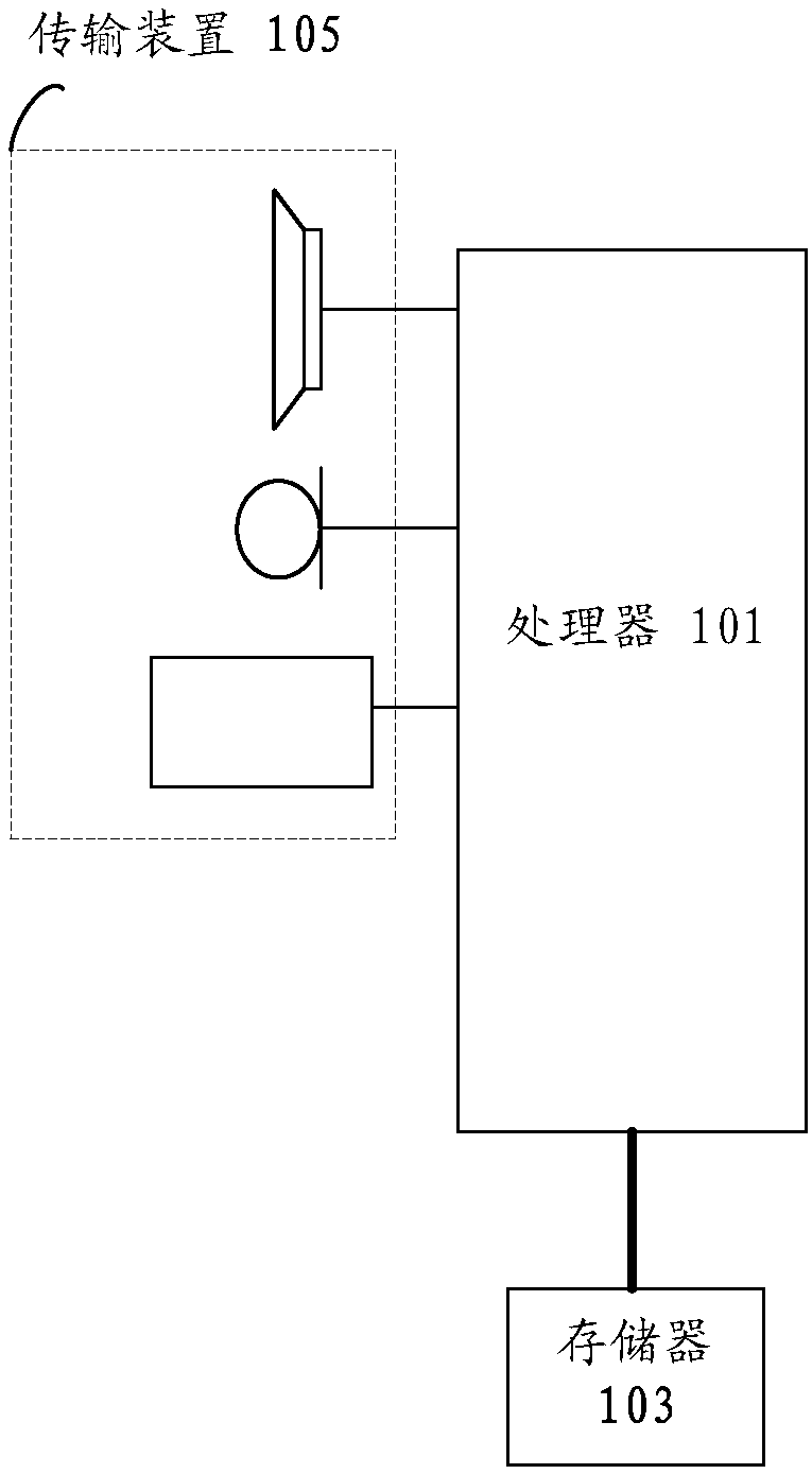
[0061] The method embodiment provided in Embodiment 1 of the present application may be executed in a mobile terminal, a computer terminal, or a similar computing device. Take running on a computer terminal as an example, such as figure 1 As shown, the computer terminal may include one or more (only one is shown in the figure) processors 101 (the processors 101 may include but not limited to processing devices such as microprocessor MCU or programmable logic device FPGA, etc.), for storing Data storage 103, and transmission means 105 for communication functions. Those of ordinary skill in the art can understand that, figure 1 The shown structure is only for illustration, and it does not limit the structure of the above-mentioned electronic device.

[0062] The memory 103 can be used to store software programs and modules of application software, such as program instructions / modules corresponding to the control method of the device in the embodiment of the present invention, ...

Embodiment approach 1

[0130] The IP network domain requests the optical network domain to create a service layer path and map it to the IP layer virtual link.

[0131] Such as Figure 7As shown, FD (Forwarding Domain, forwarding domain) identifies a device node, FD(P)-1 and FD(P)-2 are two device nodes in the IP network domain respectively, and the virtual link (ie Virtual Link) of the IP layer ) cannot intercommunicate at the IP layer, and need to intercommunicate through the optical network layer. FD-1 and FD-2 are Ethernet layer nodes in the optical network domain (the service layer of which is ODUk). LTP (Logical Terminal Point, logical terminal point) is used to identify the port, LTP-1-1 and LTP-2-1 are the source and sink ports (including source port and sink port) of the service layer path, LTP-4-1, LTP -4-2, LTP-6-1, LTP-6-2 are NNI ports of the Ethernet layer, used to generate Ethernet links, ETH FD indicates the Ethernet layer, etherlink1, etherlink2 are Ethernet links. The IP SDN Con...

Embodiment approach 2

[0139] The IP network domain requests the optical network domain to delete the service layer path.

[0140] Such as Figure 8 As shown, FD (Forwarding Domain, forwarding domain) identifies a device node, FD(P)-1 and FD(P)-2 are two device nodes in the IP network domain respectively, and the virtual link (ie Virtual Link) of the IP layer ) cannot intercommunicate at the IP layer, and need to intercommunicate through the optical network layer. FD-1 and FD-2 are Ethernet layer nodes in the optical network domain (the service layer of which is ODUk). LTP (Logical Terminal Point, logical terminal point) is used to identify the port, LTP-1-1 and LTP-2-1 are the source and sink ports of the service layer path, LTP-4-1, LTP-4-2, LTP-6 -1. LTP-6-2 is the NNI port of the Ethernet layer, which is used to generate Ethernet links. ETH FD indicates the Ethernet domain, and etherlink1 and etherlink2 are Ethernet links. The IP SDN Controller is the SDN controller of the IP network domain, ...


PUM


Abstract

The invention provides a method, apparatus and system for determining a fusion path of an IP network and an optical transport network. The method comprises the following steps: when a transmission service request crossing an optical network domain is received, allocating a virtual link meeting service requirements in an IP network domain for the transmission service; determining a target service layer path matched with the virtual link in a pre-stored service layer path, wherein the service layer path is located in the optical network domain; and sending an activation request of activating thetarget service layer path to the controller of the optical network domain. By adoption of the method, apparatus and system, the technical problem of low efficiency of providing the required service layer path for the IP layer by an optical layer in the related art is solved.

Description

technical field [0001] The present invention relates to the communication field, in particular to a path determination method, device and system for the integration of an IP network and an optical transmission network. Background technique [0002] At present, the trunk basic bearer network of operators is generally divided into two layers for construction and operation and maintenance respectively. The upper layer is an IP / MPLS (Multi-Protocol Label Switching, Multi-Protocol Label Switching) bearer network composed of routers, and the lower layer is successively composed of DWDM (Dense Wavelength Division Multiplexing, Dense Wavelength Multiplexing), Optical Transport Network (OTN, Optical Transport Network) and other components of the optical transport network (referred to as the optical layer). The IP layer proposes the optical link connection requirements between nodes to the optical layer, and the optical layer is responsible for providing statically configured optical ...

Claims


Application Information

Patent Timeline
Patent Type & Authority Applications(China)
IPC IPC(8): H04J3/16H04Q11/00
CPCH04J3/16H04Q11/00H04J3/1652H04Q11/0062
Inventor 卢刚
Owner ZTE CORP
Why Eureka
Try Eureka