Tubular type centrifuge

A tube centrifuge and feeding tube technology, applied in centrifuges and other directions, can solve the problems of labor and time waste, affecting product quality, secondary pollution, etc., to avoid damage, achieve automatic cleaning, and improve work productivity. Effect

Inactive Publication Date: 2018-06-01
武汉正天成生物科技有限公司
View PDF0 Cites 3 Cited by
  • Summary
  • Abstract
  • Description
  • Claims
  • Application Information

AI Technical Summary

Problems solved by technology

[0003] At present, the tubular centrifuges on the market are manually disassembled after the shutdown, and further manually remove and collect the centrifuged materials from the inner wall of the cylinder, resulting in a lot of labor and time waste
In the process of shutting down and dismantling materials, it is easy to cause secondary pollution and seriously affect product quality.
It cannot meet the needs of today's enterprise production. Therefore, it is urgent to develop a new type of tubular centrifuge with automatic slag discharge function.

Method used


Image

  • Tubular type centrifuge
  • Tubular type centrifuge
  • Tubular type centrifuge

Examples


Embodiment 1

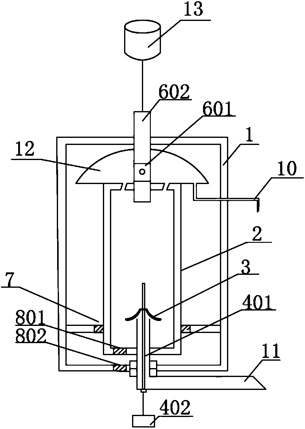
[0026] Such as figure 1 As shown, the liquid medicine to be separated and the clarifying agent are delivered to the inside of the drum 2 through the feed pipe 11; the drive shaft 602 is driven by the motor 13 to move, and the drum 2 is driven by the high-speed Form a strong centrifugal force field, use centrifugal force instead of gravity and cooperate with the flocculation of clarifier to quickly separate the clear liquid and solid particles in the liquid medicine, and the clear liquid flows out from the through hole at the upper end of the drum 2 and is collected by the liquid collecting plate 12. And flow out through the liquid outlet pipe 10; the solid residue is deposited at the bottom of the drum 2.

[0027] After the tubular centrifuge has been working for a period of time, instead of delivering liquid medicine and clarifying agent to the drum 2, the cleaning liquid or water is delivered to the inside of the drum 2 through the feed pipe 11; the side of the control nozzl...

Embodiment 2

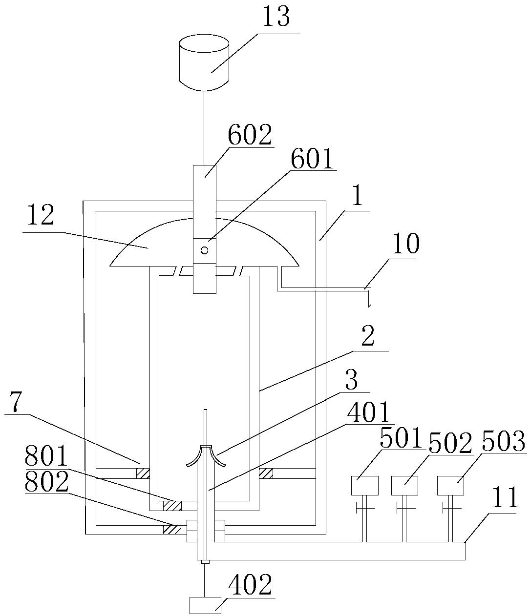
[0029] Such as figure 2 As shown, the feeding pipe 11 is connected with the liquid medicine liquid storage tank 501, the clarifying agent liquid storage tank 502, and the third liquid storage tank 503 for storing cleaning liquid or water; the liquid medicine liquid storage tank 501, the liquid medicine liquid storage tank 501, The liquid medicine and clarifier in the clarifier liquid storage tank 502 are delivered to the inside of the drum 2 through the feed pipe 11; the drive shaft 602 is driven by the motor 13 to move, and the drum 2 is driven by the drive shaft 602 and the coupling 601, A strong centrifugal force field is formed through high speed, and centrifugal force is used instead of gravity and combined with the flocculation of clarifier, so that the clear liquid and solid particles in the liquid medicine are quickly separated, and the clear liquid flows out from the through hole at the upper end of the drum 2 and is collected by the liquid collection plate. 12, and ...


PUM


Abstract

The invention discloses a tubular type centrifuge. The tubular type centrifuge comprises a barrel, a rotary drum, a liquid collecting plate, a feeding tube and a liquid draining tube, wherein the rotary drum is coaxially mounted in the barrel; the upper end of the rotary drum is connected with a driving shaft through a coupler; the bottom of the rotary drum communicates with the feeding tube; an annular slide way is arranged between a side of the rotary drum and the barrel, so that the rotary drum rotates stably; through holes are formed in the upper end of the rotary drum; the liquid collecting plate is coaxially mounted at the upper end of the rotary drum; during high-speed running of the rotary drum, separated liquid flows to the liquid collecting plate via the through holes; the liquiddraining tube is arranged on the bottom of the liquid collecting plate; and an ultrasonic waveguide rod is coaxially arranged on a vertical portion of the feeding tube, and is electrically connectedwith a peripheral ultrasonic generation source. According to the tubular type centrifuge, the rotary drum which does not need to be taken out can be automatically and thoroughly cleaned.

Description

technical field [0001] The invention belongs to the technical field of separation equipment, and in particular relates to a tubular centrifuge. Background technique [0002] A centrifuge is a machine that uses centrifugal force to separate components in a mixture of liquid and solid particles or liquid and liquid. The centrifuge is mainly used to separate the solid particles in the suspension from the liquid, or to separate two different densities and immiscible liquids in the emulsion. Centrifuges are widely used in chemical industry, petroleum, food, pharmaceutical, mineral processing, coal, water treatment and shipbuilding and other departments. There are two series of tubular centrifuges, GF and GQ, such as GQ series clarification tubular centrifuges and GF series liquid-liquid separation tubular centrifuges. GF separation type is mainly used to separate various difficult-to-separate emulsions, especially suitable for liquid-liquid separation with little difference in ...

Claims


Application Information

Patent Timeline
Patent Type & Authority Applications(China)
IPC IPC(8): B04B5/10B04B15/06
CPCB04B5/10B04B15/06
Inventor 刘海军曹海丽
Owner 武汉正天成生物科技有限公司
Why Eureka
Try Eureka