Tin bar cutting machine

A bar cutting machine and cutting machine technology, applied in metal processing equipment, feeding devices, positioning devices, etc., can solve the problems of easy oxidation of tin bars, large cutting noise, low efficiency, etc., and achieve the effect of expanding the scope of use

Pending Publication Date: 2018-06-01
VICTORY TECH INT
View PDF6 Cites 0 Cited by
  • Summary
  • Abstract
  • Description
  • Claims
  • Application Information

AI Technical Summary

Problems solved by technology

[0002] In the field of tin solder production, the production of tin rods adopts a manual operation mode, that is, the liquid tin in the molten state is put into the casting pot, and the tin liquid is poured into the mold by holding the casting pot by hand. After the tin liquid is solidified, the tin rod is removed from the There are many disadvantages in this mode of operation. First, this production method is labor-intensive and the production efficiency is extremely low. Secondly, due to the high temperature of the tin liquid, manual operation is very easy to burn, and there is a great potential safety hazard. Thirdly, manual operation is adopted. During the casting process, due to the long contact time between the tin...

Method used


Image

  • Tin bar cutting machine
  • Tin bar cutting machine
  • Tin bar cutting machine

Examples


Embodiment Construction

[0035] The implementation of the present invention will be described in detail below in conjunction with the accompanying drawings. The accompanying drawings are only for reference and description, and do not constitute a limitation to the protection scope of the present invention.

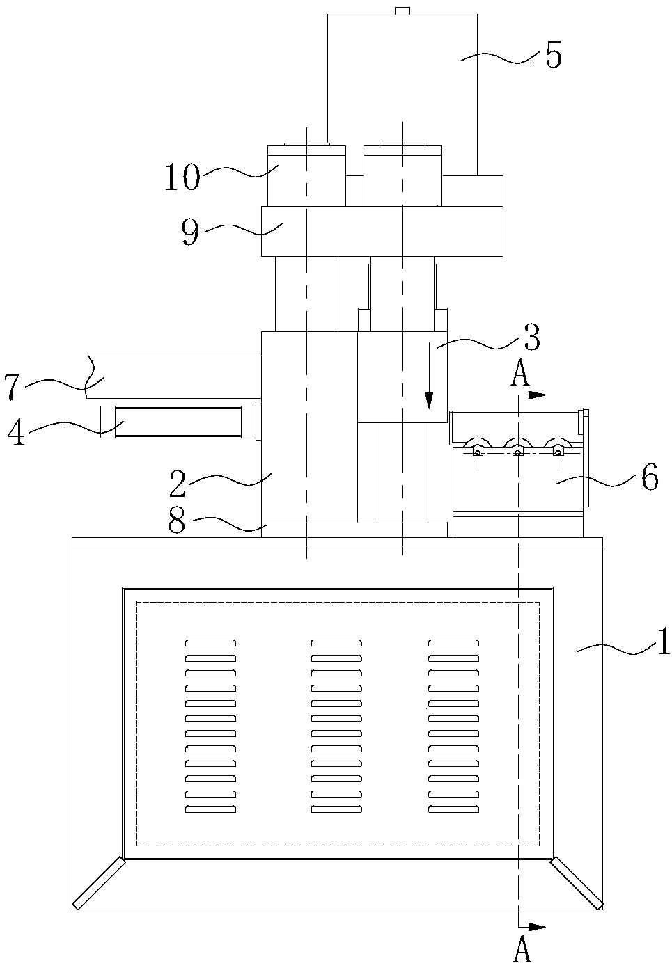
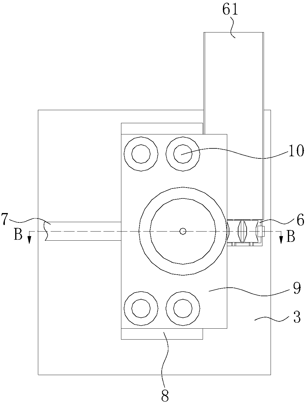
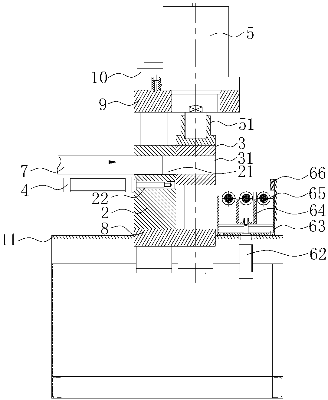
[0036] refer to Figure 1 to Figure 4 , a kind of tin rod cutting machine, comprises frame 1, the lower support plate 8 that is fixed on the frame 1, the fixed module 2 that is fixed on the lower support plate 8, the pushing device 4 that is arranged on the fixed module 2, is arranged on The upper support plate 9 on the upper end of the fixed module 2, the shearing pusher 5 fixed on the upper support plate 9, the moving module 3 which is arranged on one side of the fixed module 2 and moves up and down along the side of the fixed module 2 controlled by the shear pusher 5, Four guide pillars 10 fixed on the frame 1 to connect the upper support plate 9 and the lower support plate 8 and a retractable ...


PUM


Abstract

The invention discloses a tin bar cutting machine. The tin bar cutting machine includes a rack. The rack is fixedly provided with a fixed module. One side of the fixed module is provided with a movingmodule controlled by a cutting pushing device to move up and down along the side surface of the fixed module. The other side, corresponding to the fixed module, of the rack is provided with a material collecting device capable of jacking out the bin bar and making the bin bar to slide down obliquely. The fixed module is provided with a material pushing through hole horizontally and a material feeding through hole capable of allowing the tin bar to penetrate through horizontally. The feeding through hole is located over the material pushing through hole. The moving module is horizontally provided with a discharging through hole in butt joint with the feeding through hole. According to the tin bar cutting mechanism, when the tin bar horizontally penetrates through the moving module and thefixed module simultaneously, the moving module moves downwards to cut the tin bar, the material pushing device pushes the tin bar out of the moving module horizontally; the material collecting deviceautomatically jacks out the tin bar to conduct material collecting; the phenomenon of material sticking or adhesion is prevented from appearing during cutting; meanwhile, the cutting noise is low, andthe material collecting efficiency is high.

Description

technical field [0001] The invention belongs to the technical field of tin bar processing equipment, in particular to a tin bar cutting machine. Background technique [0002] In the field of tin solder production, the production of tin rods adopts a manual operation mode, that is, the liquid tin in the molten state is put into the casting pot, and the tin liquid is poured into the mold by holding the casting pot by hand. After the tin liquid is solidified, the tin rod is removed from the There are many disadvantages in this mode of operation. First, this production method is labor-intensive and the production efficiency is extremely low. Secondly, due to the high temperature of the tin liquid, manual operation is very easy to burn, and there is a great potential safety hazard. Again, manual operation is adopted. During the casting process, due to the long contact time between the tin liquid and the air, the surface of the tin rod is easily oxidized to produce impurities, whi...

Claims


Application Information

Patent Timeline
IPC IPC(8): B21D28/02B21D45/04B21D43/20
CPCB21D28/02B21D43/20B21D45/04
Inventor 蔡永忠黄广财
Owner VICTORY TECH INT
Why Eureka
Try Eureka