Polishing machine
A grinding machine and grinding mechanism technology, applied in the direction of grinding frame, grinding machine, grinding machine parts, etc., can solve the problem of small adjustment range of grinding machine, and achieve the effect of flexible grinding, increasing range and improving grinding efficiency.
- Summary
- Abstract
- Description
- Claims
- Application Information
AI Technical Summary
Problems solved by technology
Method used
Image

Examples
Embodiment Construction
[0017] The present invention is described in further detail now in conjunction with accompanying drawing. These drawings are all simplified schematic diagrams, which only illustrate the basic structure of the present invention in a schematic manner, so they only show the configurations related to the present invention.
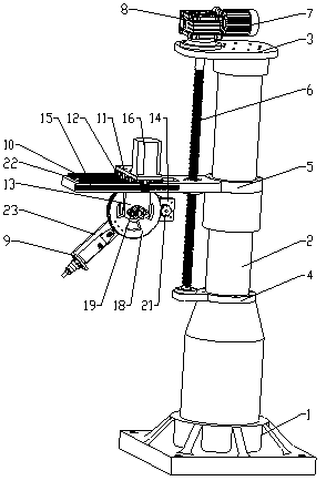
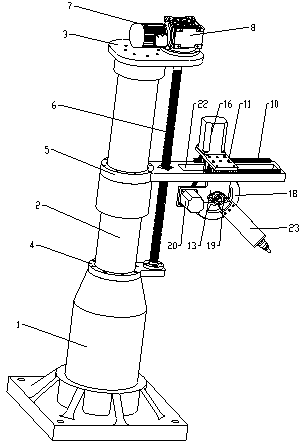
[0018] Such as figure 1 and figure 2 As shown, a grinding machine includes a base 1, a base shaft 2, a top plate 3, a bottom plate 4, a beam 5 for fixing the grinding mechanism, a screw rod 6, a third driving device and a grinding mechanism, and the base 1 and the base shaft 2 are fixed Connection, the top of the seat shaft 2 is fixedly connected with the top plate 3, the lower part of the seat shaft 2 is fixedly connected with the bottom plate 4, one end of the beam 5 is slidably connected to the seat shaft 2, the other end of the beam 5 is fixedly connected with the grinding mechanism, and the beam 5 is set on the top plate 3 and the bottom plate 4, the t...
PUM
 Abstract
Description
Claims
Application Information