
Automatic grinding device for plastic part joint lines

A parting line, plastic parts technology, applied in grinding/polishing equipment, metal processing equipment, grinding machines, etc., can solve the problems of difficult to meet the requirements of grinding effect, high labor cost, low efficiency, etc., to achieve fast action and comprehensive grinding , Improve the effect of grinding accuracy

Inactive Publication Date: 2018-06-01
东莞顶钧塑胶模具有限公司
View PDF0 Cites 5 Cited by
  • Summary
  • Abstract
  • Description
  • Claims
  • Application Information

AI Technical Summary

Problems solved by technology

For a long time, the grinding of plastic parts has generally been done manually with grinding consumables, or with hand-held plastic parts on a grinder. This method of grinding the mold line is expensive, time-consuming, and extremely inefficient, and the grinding effect is difficult to meet the requirements.

Method used


Image

  • Automatic grinding device for plastic part joint lines
  • Automatic grinding device for plastic part joint lines
  • Automatic grinding device for plastic part joint lines

Examples


Embodiment 1

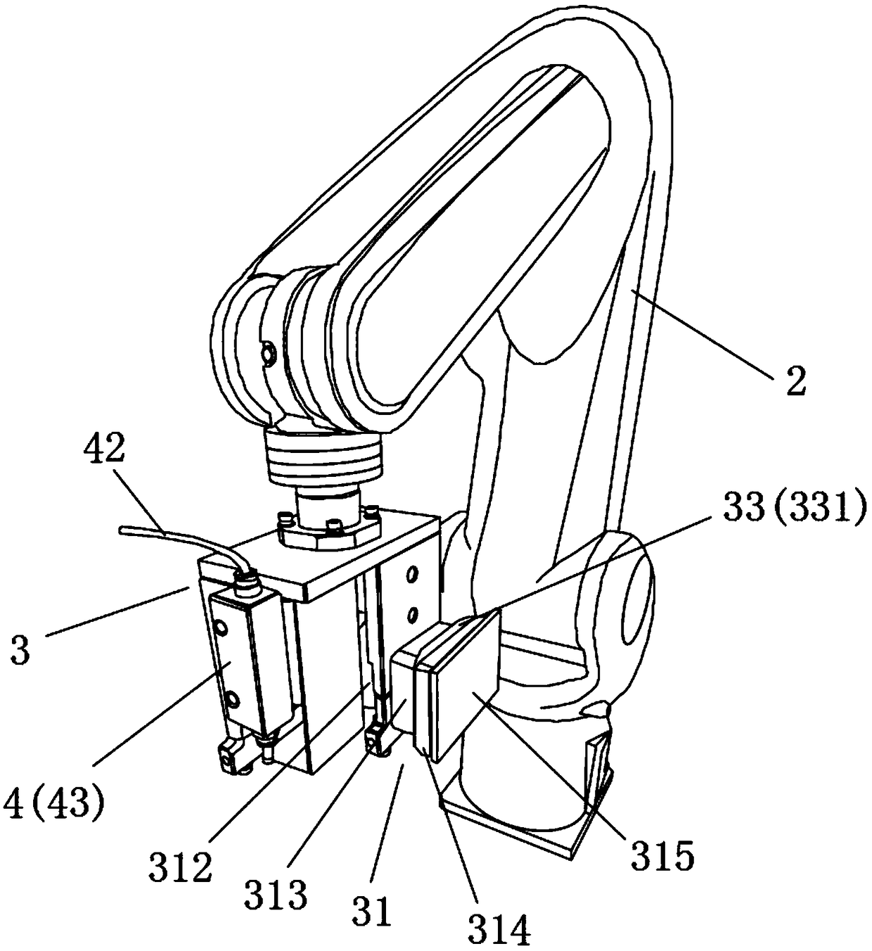
[0026] Please refer to figure 1 , This embodiment provides an automatic grinding equipment for a mold clamping line for plastic parts, including a machine, a mechanical arm 2 arranged on the machine, and a grinding device arranged at the end of the mechanical arm 2 and capable of rotating 360° freely 3. The grinding device 3 includes a rough grinding mechanism 31, which includes a rough grinding drive cylinder, a rough grinding pneumatic cam 312 connected to the rough grinding drive cylinder, and a rough grinding mechanism connected to the rough grinding pneumatic cam 312 Base 313, a rough grinding elastic grinding head 314 arranged on the outer end surface of the rough grinding base 313, and a rough sandpaper 315 pasted on the outer end surface of the rough grinding elastic grinding head 314; the rough grinding drives the cylinder and the rough grinding pneumatically Driven by the cam 312, the rough-grinding elastic sanding head 314 vibrates along a preset sanding track, and th...

Embodiment 2

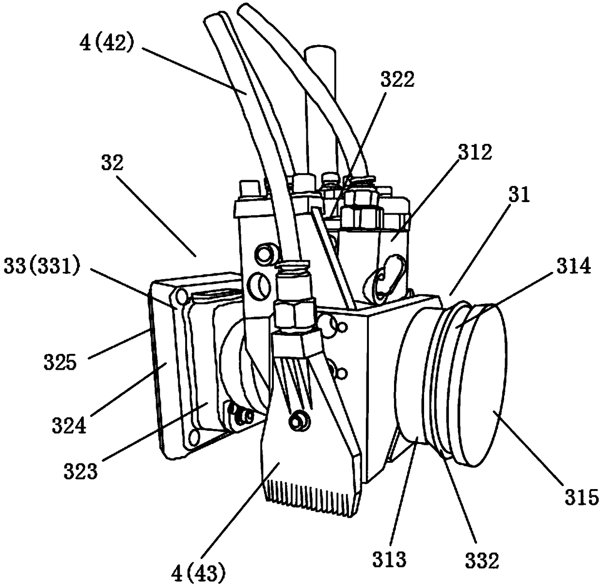
[0030] Please refer to figure 2 The main difference between this embodiment and the first embodiment is that the grinding device 3 also includes a fine grinding mechanism 32, which is located on the same line as the rough grinding mechanism 31, and the fine grinding mechanism 32 includes a fine grinding mechanism 32. Grinding driving cylinder, a fine grinding pneumatic cam 322 connected to the fine grinding driving cylinder, a fine grinding base 323 connected to the fine grinding pneumatic cam 322, and a fine grinding elastic grinding head arranged on the outer end surface of the fine grinding base 323 324, and a fine sandpaper 325 pasted on the outer end surface of the fine grinding elastic grinding head 324; when the surface smoothness of the plastic part is more stringent, the surface of the mold line needs to be further finely ground, and the fine grinding drives the cylinder Driven by the fine-grinding pneumatic cam 322, the fine-grinding elastic grinding head 324 vibrates...

Embodiment 3

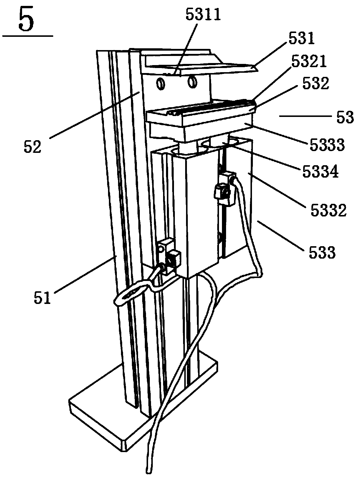
[0036] Please refer to image 3 Compared with the first or second embodiment, the main difference between this embodiment and the first or second embodiment is that: the automatic grinding equipment for the mold clamping line of plastic parts also includes an automatic sandpaper removal device 5 arranged on the machine table and located on the side of the robot arm 2. The automatic sandpaper removal device 5 includes a mounting side plate 51 arranged on the machine table, a mounting base plate 52 arranged on the inner side of the mounting side plate 51 and facing the robot arm 2, and a mounting base plate 52 arranged on the inner side of the mounting base plate 52 A sandpaper gripping mechanism 53, wherein the sandpaper gripping mechanism 53 includes an upper splint 531 fixed to the upper part of the inner side of the mounting base 52, and a lower splint movably arranged on the inner side of the mounting base 52 and directly below the upper splint 531 532, and an up-and-down dri...


PUM


Abstract

The invention discloses an automatic grinding device for plastic part joint lines. The automatic grinding device comprises a machine table, a mechanical arm and a grinding device body, the mechanicalarm is arranged on the machine table, the grinding device body is arranged at the end of the mechanical arm and can freely rotate by 360 degrees, the grinding device body comprises a coarse-grinding mechanism, the coarse-grinding mechanism comprises a coarse-grinding driving cylinder, a coarse-grinding pneumatic cam, a coarse-grinding base, a coarse-grinding elasticity grinding head and raw emerypaper, the coarse-grinding pneumatic cam is connected to the coarse-grinding driving cylinder, the coarse-grinding base is connected to the coarse-grinding pneumatic cam, the coarse-grinding elasticity grinding head is arranged on the outer end surface of the coarse-grinding base, the raw emery paper is stuck on the outer end surface of the coarse-grinding elasticity grinding head, the coarse-grinding driving cylinder and the coarse-grinding pneumatic cam drive the coarse-grinding elasticity grinding head to move along a preset grinding track in a vibration manner, and the joint lines on the plastic parts are comprehensively and coarsely grinded by the raw emery paper on the end surface of the coarse-grinding elasticity grinding head in a vibration manner. According to the automatic grinding device, the joint lines can be comprehensively, seamlessly, rapidly, accurately, coarsely and finely grinded. Compared with a manual grinding mode, grinding efficiency is greatly improved, and grinding accuracy is improved.

Description

Technical field [0001] The invention relates to a polishing equipment, in particular to an automatic polishing equipment for a plastic part moulding line. Background technique [0002] The parting line is also called the flashing line. Excess plastic flows out at the joint of the mold, leaving visible traces after cutting off the overflow. Sometimes it is called the mold mark or the interface line core. It also refers to the gap between the mold parts due to the material flowing into the mold. The seam produced on the plastic or casting, or the joint under the main model of the plastic mold, is used to indicate that the plastic mold is divided into two halves or several parts. [0003] The parting line seriously affects the appearance of the plastic parts, so the plastic parts must be polished before plating and spraying. For a long time, the grinding of plastic parts is generally manual grinding with grinding consumables, or hand-held plastic parts are ground on a grinding machin...

Claims


Application Information

Patent Timeline
Patent Type & Authority Applications(China)
IPC IPC(8): B24B9/02B24B41/04B24B47/20B25J11/00
CPCB24B9/02B24B41/04B24B47/20B25J11/0065
Inventor 陈进源
Owner 东莞顶钧塑胶模具有限公司
Learn More