Robot control device, a robot control method, and a picking device

A technology for controlling equipment and robots, applied in the direction of program control manipulator, program control, general control system, etc., can solve the problems of expensive force sensor, high cost, easy damage, etc.

Inactive Publication Date: 2018-06-01
KK TOSHIBA
View PDF0 Cites 7 Cited by
  • Summary
  • Abstract
  • Description
  • Claims
  • Application Information

AI Technical Summary

Problems solved by technology

However, force sensors are expensive and prone to breakage
Instead of a force sensor, even if a mechanism to detect contact force is attached, it becomes a factor of high cost

Method used


Image

  • Robot control device, a robot control method, and a picking device
  • Robot control device, a robot control method, and a picking device
  • Robot control device, a robot control method, and a picking device

Examples


no. 1 example

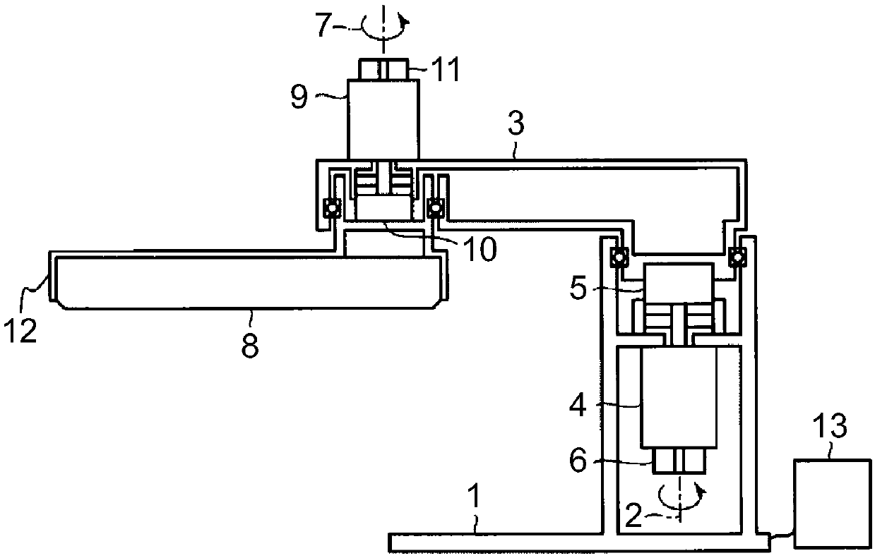
[0023] will refer to figure 1 Let's explain the first embodiment. figure 1 is one example of a cross-sectional view of a two-link robot arm that is a control target of the robot control apparatus according to the first embodiment.

[0024] For this mechanical arm, one end of the first link 3 is mounted on the upper part of the base 1 . The other end of the first link 3 is mounted to the second link 8 .

[0025] The base 1 includes a first motor 4 , a first reduction gear 5 and a first encoder 6 . The first link 3 includes a second motor 9 , a second reduction gear 10 and a second encoder 11 . The end of the second link 8 includes a payload 12 . With the payload 12 at the end of the second link 8 , the robotic arm contacts the work object (job).

[0026] In the robot control device 13, the first link 3 rotates planarly around the first shaft 2 as the center by the combination of the first motor 4, the first encoder 6 and the first reduction gear 5 (having a spring characte...

no. 2 example

[0115] will refer to Figure 8 The second embodiment will be explained. Figure 8 One example of the observer section of the robot control device according to the second embodiment is shown.

[0116] In the observer section of the second embodiment, the estimated value of the torsional velocity is output instead of the estimated value of the torsional acceleration, which is different from the robot control apparatus of the first embodiment. Other components are the same as those of the robot control device of the first embodiment.

[0117] Such as Figure 8 As shown, the estimated value of the torsional angular velocity used to derive the estimated value of the torsional velocity is calculated from the difference between the estimated value of the angular velocity of each link and the estimated value of the angular velocity of each motor.

[0118] In detail, in this observer 131, based on the estimated value of the angular velocity of the first link 3, the speed of the firs...

no. 3 example

[0121] will refer to Figure 10 The third embodiment will be explained. Figure 10 One example of the observer section of the robot control device according to the third embodiment is shown.

[0122] In the observer section of the third embodiment, instead of the estimated value of torsional acceleration, a PI control output value is output, which is different from the robot control apparatus of the first embodiment. Other components are the same as those of the robot control device of the first embodiment.

[0123] Such as Figure 10 As shown, using Δu output from PI controllers 1311 and 1312 respectively 1 and Δu 2 . The PI control output value includes the estimation error of the observer section and the external disturbance torque. Therefore, by setting this threshold, only the external disturbance torque can be extracted.

[0124] Figure 11A waveform of an estimated PI control output value when a touch operation is performed is shown.

[0125] exist Figure 11 ...


PUM


Abstract

The invention relates to a robot control device, a robot control method, and a picking device. According to one embodiment, the robot control device is used for a mechanical arm including a linkage rod and a motor used for rotationally driving the linkage rod. The robot control device includes a derivation part. The derivation part derives a first estimated value including a variation of a rotation angle of the link and a second estimated value including a variation of a rotation angle of the motor, based on an angular velocity and a current reference value of the motor. Furthermore, the derivation part derives an external force generated to the robot arm, based on a difference between the first estimated value and the second estimated value.

Description

[0001] Cross References to Related Applications [0002] This application is based on and claims priority from Japanese Patent Application No. 2016-229327 filed on November 25, 2016; the entire contents of which are incorporated herein by reference. technical field [0003] Embodiments described herein relate generally to robot control devices, robot control methods and picking devices. Background technique [0004] In an automation line using a robot arm, a worker performs work called "teaching" to store position data of the tip of the arm in advance. Teaching takes time and labor, and the burden on workers is great. Therefore, workers need to be uneducated. To perform teaching-free, the robot uses both vision sensors and force sensors. However, the vision sensor has an error in the depth direction, and a vision sensor with high precision requires high cost. In addition, in the case of using a force sensor mounted on the tip of the robot arm, the depth direction can be ...

Claims


Application Information

Patent Timeline
Patent Type & Authority Applications(China)
IPC IPC(8): B25J13/00B25J9/16
CPCB25J9/1602B25J9/161B25J13/00G05B2219/39186B25J9/1676G05B2219/41374G05B2219/39355B25J9/1633B25J9/1638G05B2219/39353G05B2219/41387
Inventor 大明准治
Owner KK TOSHIBA
Why Eureka
Try Eureka