Traveling wheel mechanism with automatic lifting function and for rail trolley

A technology of automatic lifting and traveling wheels, applied in railway car body parts, bogies, transportation and packaging, etc., can solve the problems of testing equipment, testing equipment and personnel safety hazards, rubber tire oil corrosion, and high center of gravity of equipment. , to achieve the effect of compact structure, no damage to the track, and not easy to derail

Pending Publication Date: 2018-06-01
CSIC NO 710 RES & DEV INST
View PDF10 Cites 1 Cited by
  • Summary
  • Abstract
  • Description
  • Claims
  • Application Information

AI Technical Summary

Problems solved by technology

However, the disadvantage of rubber tires is that they are large in size, so that the height of the trolley is high, so that the center of gravity of the equipment is high, and the rubber tire itself is easily affected by the corrosion of oil, the impact of changes in the test environment, and the alternating vibration and shock generated when the equipment is running at high speed. Due to the action of force, the tire will suddenly fail during the whole process of the environmental test
In addition, rubber tires are prone to derailment when traveling on I-shaped tracks.
This situation will also bring great potential safety hazards to test equipment, test testing equipment and personnel.

Method used


Image

  • Traveling wheel mechanism with automatic lifting function and for rail trolley
  • Traveling wheel mechanism with automatic lifting function and for rail trolley
  • Traveling wheel mechanism with automatic lifting function and for rail trolley

Examples


Embodiment Construction

[0029] The present invention will be further described in detail below with reference to the drawings and embodiments.

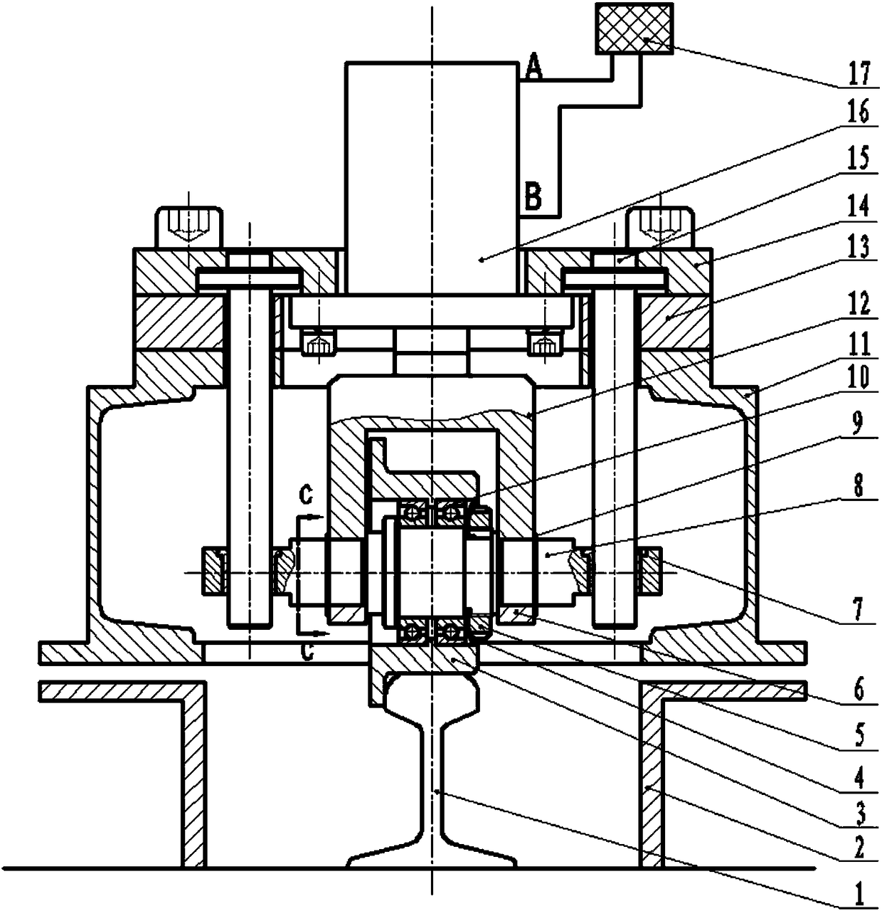
[0030] This embodiment provides a traveling wheel mechanism with automatic lifting function for rail trolleys. The mechanism has convenient operation, compact structure, simple processing technology, heavy bearing capacity, no derailment, flexible travel, no damage to the track, stable lifting, etc. Features, can realize safe and reliable travel, lifting and tightening limit between rail trolley and I-shaped track.

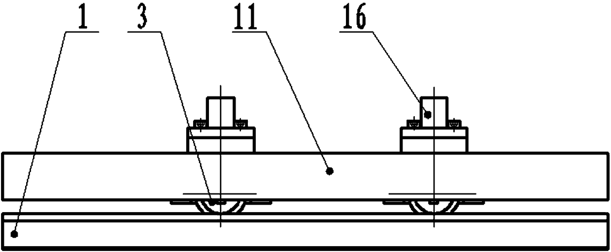
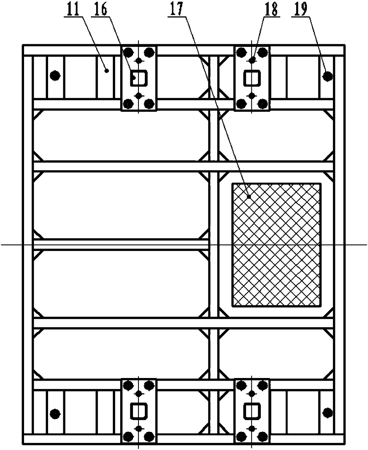
[0031] Such as figure 1 with figure 2 As shown, the traveling wheel mechanism with automatic lifting function includes: a traveling structure, a hydraulic lifting structure and a fastening and limiting structure; the I-shaped track 1 is matched with it.

[0032] The traveling structure includes: traveling wheel 3, axle 8 and traveling wheel mounting bracket 12. The selected material of the axle 8 is 40Cr quenched and tempered material, which has good...


PUM


Abstract

The invention relates to a traveling wheel mechanism with an automatic lifting function and for a rail trolley. The walking wheel mechanism has an advancing function, a hydraulic lifting function anda fastening limiting function, and can achieve safe and reliable advancing, ascending, descending and fastening limiting between the rail trolley and an H-shaped rail. The traveling wheel mechanism comprises an advancing structure, a hydraulic lifting structure and a fastening limiting structure; the advancing structure comprises an advancing wheel matched with the H-shaped rail; the hydraulic lifting structure comprises a hydraulic oil cylinder used for driving the advancing wheel to ascend or descend to be separated from or make contact with the H-shaped rail; when the traveling wheel is incontact with the H-shaped rail, the rail trolley is supported on the H-shaped rail through the traveling wheel, and at the moment, the rail trolley is in an advancing state; when the traveling wheel is separated from the H-shaped rail, the rail trolley is supported on supporting frames on the two sides of the H-shaped rail, and the rail trolley and the supporting frames are fastened and limited through the fastening limiting structure, and at the moment, the rail trolley is in a fastening limiting state.

Description

Technical field [0001] The invention relates to a traveling wheel mechanism, in particular to a traveling wheel mechanism with an automatic lifting function, and belongs to the technical field of mechanical design. Background technique [0002] A certain type of equipment needs to undergo a series of environmental tests. Before the test, the equipment is placed on the rail trolley by a crane, and then the rail trolley is transported along the I-shaped track to a specific location in different environmental test boxes for corresponding tests. Assess the environmental resistance function and performance of the equipment. [0003] Due to the heavy weight of this type of equipment, and the need to continuously switch the equipment at high speed for a long time during the test, the inertial impact force is very large; at the same time, the rail trolley carrying the test equipment needs to be frequently moved to the corresponding position during the test. . If the limit cannot be safel...

Claims


Application Information

Patent Timeline
Patent Type & Authority Applications(China)
IPC IPC(8): B61F5/00
CPCB61F5/00
Inventor 姚涛刘威张雳张仁花程林风
Owner CSIC NO 710 RES & DEV INST
Why Eureka
Try Eureka