Ceramic superconducting high-pressure rotary cutting blockage removal device

A high-pressure spinning and superconducting technology, used in packaging, transportation, packaging, containers, etc., can solve the problems of long construction period, high cost, and large amount of modification engineering, achieving high degree of automation, low labor intensity, and good blocking effect. Effect

Pending Publication Date: 2018-06-01
河南鼎盛铝业有限公司
View PDF0 Cites 4 Cited by
  • Summary
  • Abstract
  • Description
  • Claims
  • Application Information

AI Technical Summary

Problems solved by technology

The rotary unblocking machine is only suitable for circular silos and hyperbolic silos, and has limitations for rectangular silos. Moreover, these methods of silo

Method used


Image

  • Ceramic superconducting high-pressure rotary cutting blockage removal device
  • Ceramic superconducting high-pressure rotary cutting blockage removal device

Examples


Example Embodiment

[0018] Specific implementation method

[0019] The technical scheme of the present invention will be further described below in conjunction with the drawings.

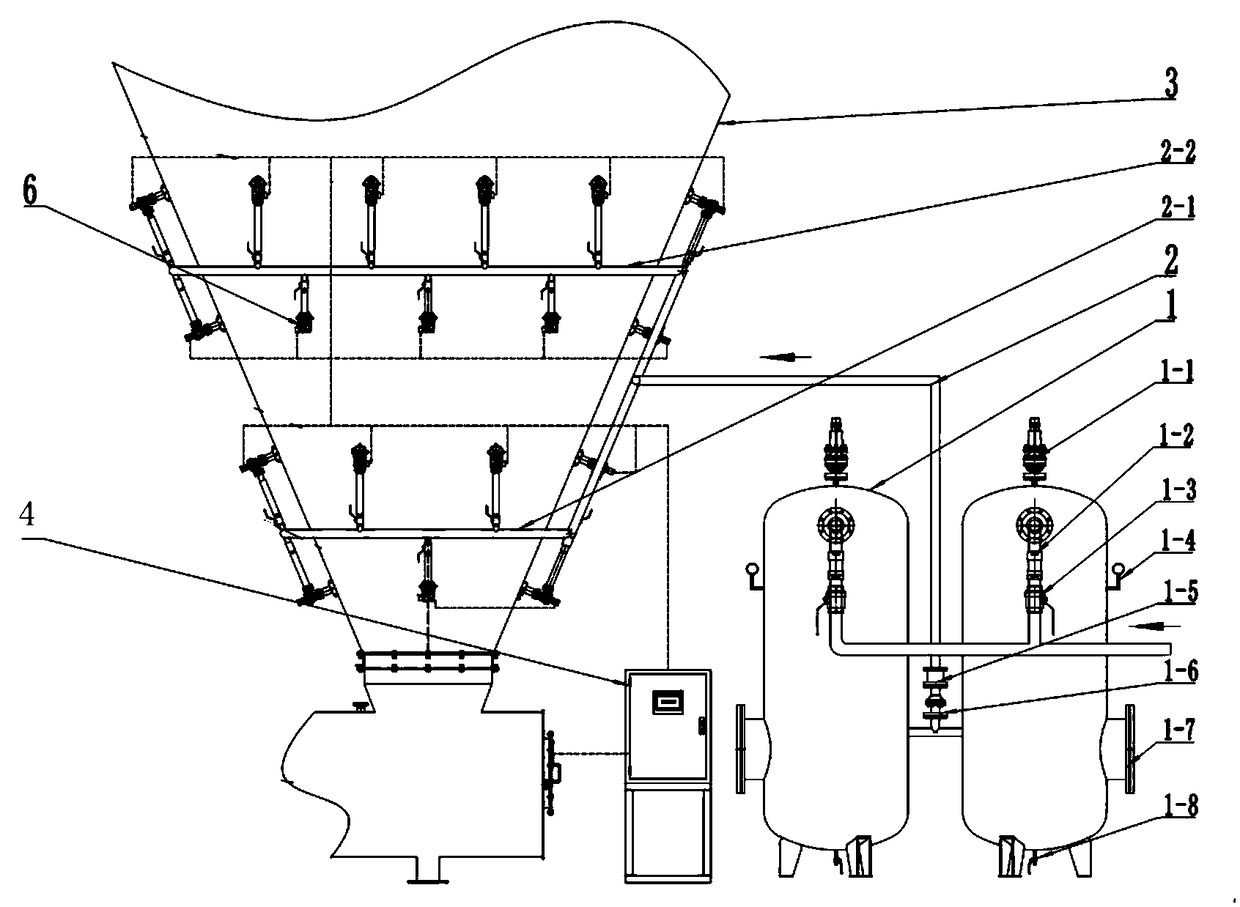
[0020] Such as Figure 1-2 As shown, the ceramic superconducting high-pressure rotary cutting device of the present invention includes: a gas storage tank 1, a gas pipe 2, a PLC control cabinet 4, and a number of ceramic nozzle groups 6;

[0021] Wherein, the top of the gas storage tank 1 is provided with a safety valve 1-1, the safety valve 1-1 is connected to one end of the air intake check valve 1-2, and the other of the air intake check valve 1-2 One end is connected to one end of the air inlet valve 1-3, the other end of the air inlet valve 1-3 is connected to one end of the air pipe 2, and the air pipe 2 is connected to one end of the air branch pipe 2-1, so The other end of the gas branch pipe 2-1 is connected to the air inlets of the ceramic nozzle groups 6 respectively, and the ceramic nozzle groups are arranged in...


PUM

PropertyMeasurementUnit
Diameteraaaaaaaaaa

Abstract

The invention discloses a ceramic superconducting high-pressure rotary cutting blockage removal device, and belongs to the technical field of thermal power plant coal conveying. The blockage removal device comprises a gas storage tank, a gas conveying pipe, a PLC control cabinet and a plurality of ceramic nozzle sets; gas is sprayed downwards into a stock bin from ceramic nozzles through the gas conveying pipe, materials on the wall of the stock bin is impacted by kinetic energy generated by high-pressure air, thus, the materials are scattered, loosened and disengaged from the wall of the stock bin to move downwards, and accordingly, the stock bin blockage problem is solved. The ceramic superconducting high-pressure rotary cutting blockage removal device has the technical characteristics that the shape structure of an original coal bin is not changed, only a small hole is formed in the wall of the coal bin, and then, the blockage removal device can be fixed to the outer wall of the coal bin and is suitable for stock bins of various shapes; and the structure is simple, installation and maintenance are convenient, and the blockage removal effect is good.

Description

technical field [0001] The invention discloses a ceramic superconducting high-pressure rotary cutting blockage removal device, which belongs to the technical field of coal transportation in thermal power plants. Background technique [0002] The current form of coal bunkers can be divided into rectangular conical funnel bins, cylindrical bins, and hyperbolic bins. When the material enters the coal bunker, since the structure of various bunkers has a large entrance and a small exit, the friction between the materials and between the materials and the bin wall increases during the falling process of the materials. When the materials cannot rely on their own gravity to overcome the friction When the pressure is high, the material cannot slip out of the warehouse, which often causes the material to be blocked; and because the moisture content of the material is high, the particle size is very fine, and the sum of the particle surfaces per unit volume is very large, so the cohesi...

Claims


Application Information

Patent Timeline
IPC IPC(8): B65D88/70B65D90/00
CPCB65D88/703B65D90/00
Inventor 赵云辉赵星
Owner 河南鼎盛铝业有限公司
Why Eureka
Try Eureka