High-precision gradient loss detection method and device based on ultrasonic sensor

A loss detection, ultrasonic technology, applied in escalators, transportation and packaging, etc., can solve the problems of poor practicability, achieve the effect of avoiding poor practicability, high precision, and promoting detection accuracy

Active Publication Date: 2018-06-01
中景恒基云端物联网科技成都有限公司
View PDF5 Cites 0 Cited by
  • Summary
  • Abstract
  • Description
  • Claims
  • Application Information

AI Technical Summary

Problems solved by technology

[0003] The purpose of the present invention is: the present invention provides a high-precision step loss detection method and device based on an ultrasonic sensor, which solves the problem that the existing detection method uses ultrasonic infrared diffuse reflection to sense a fixed distance, resulting in poor practicability

Method used


Image

  • High-precision gradient loss detection method and device based on ultrasonic sensor
  • High-precision gradient loss detection method and device based on ultrasonic sensor
  • High-precision gradient loss detection method and device based on ultrasonic sensor

Examples


Embodiment 1

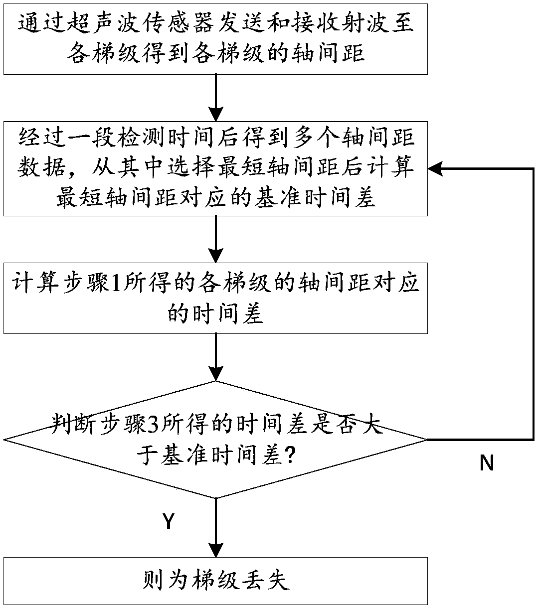
[0037] A high-precision step loss detection method based on ultrasonic sensors includes the following steps:

[0038] Step 1: Use the ultrasonic sensor to send and receive radio waves to each step to obtain the axis distance of each step;

[0039] Step 2: After a period of detection time, multiple axis distance data are obtained, and the shortest axis distance is selected from among them, and the reference time difference corresponding to the shortest axis distance is calculated;

[0040] Step 3: Calculate the time difference corresponding to the axis spacing of each step obtained in Step 1;

[0041] Step 4: Determine whether the time difference obtained in step 3 is greater than the reference time difference, if it is greater than the step loss; if not, skip to step 2.

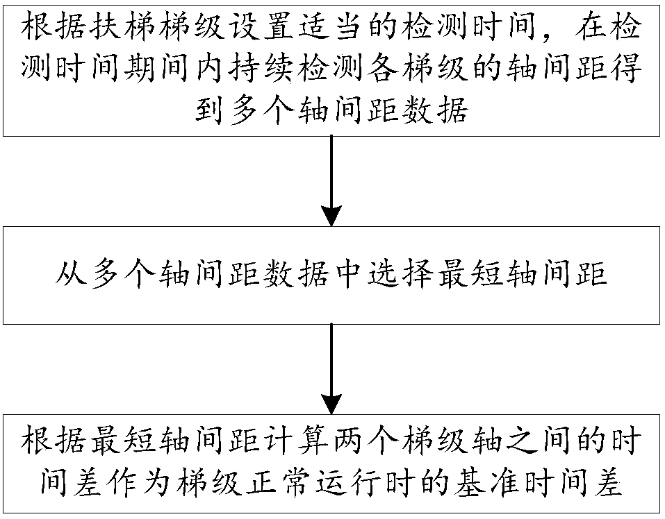
[0042] Step 2 includes the following steps:

[0043] Step 2.1: Set an appropriate detection time according to the escalator step, and continuously detect the axis distance of each step during the detection time to obtai...

Embodiment 2

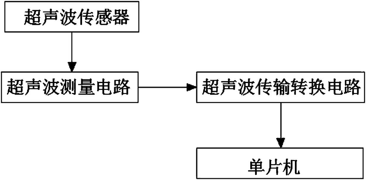
[0056] An ultrasonic sensor-based high-precision step loss detection method and device, including the following steps: first send and receive radio waves through the ultrasonic sensor, the ultrasonic measurement circuit performs waveform signal measurement and processing, and then converts the processed waveform signal through the waveform-serial port After the chip, analog-to-digital conversion unit and signal isolation chip are converted, they are transmitted to the single-chip microcomputer. The single-chip microcomputer calculates the step-axis spacing. After a detection time of 5-10 minutes, the single-chip microcomputer calculates the shortest step-axis spacing during the detection time. Calculate the reference time difference between the corresponding step axis, according to the calculation reference time difference is 1.5s; because each step corresponds to a step axis, if the step is lost, the time difference corresponding to the step axis spacing will be greater than the...


PUM


Abstract

The invention discloses a high-precision gradient loss detection method and a device based on an ultrasonic sensor, and relates to the field of gradient loss of ultrasonic detection. The method comprises the following steps that 1, a radio wave is transmitted and received to each gradient through the ultrasonic sensor to obtain axial spacing of each gradient; 2, a plurality of shaft distance datais obtained through a detection time, and reference time difference corresponding to the shortest shaft distance is calculated after the shortest shaft distance is selected from the shaft distance data; 3, the time difference corresponding to the shaft spacing of each gradient obtained in the step 1 is calculated; and 4, whether the time difference obtained in the step 3 is larger than the reference time difference or not is judged, if yes, the gradient is lost, and if not, the step 2 is executed. The problem that the practicability is poor due to the fact that an existing detection method adopts the ultrasonic infrared diffuse reflection induction fixing distance is solved, so that the effect of accurately detecting the gradient loss by detecting the shortest distance corresponding to different escalators is achieved.

Description

Technical field [0001] The invention relates to the field of ultrasonic detection of step loss, in particular to a high-precision method and device for detecting step loss based on an ultrasonic sensor. Background technique [0002] When the escalator is in operation, due to man-made or long-term use of the steps, a certain step falls instantaneously, and there is a dangerous situation of an elevator cavity. Then the equipment needs to be detected in time for the missing step cavity to avoid safety accidents. If it happens, the missing steps of the escalator have a significant impact on the safety of the escalator. According to the regulations, “the missing step monitoring device of the field equipment should be installed next to the upper and lower step sag protection devices. The inspection method: remove 1 step or pedal, Run the gap to the position of the straight section in the return branch that is connected to the lower part of the revolving section, and start the equipment...

Claims


Application Information

Patent Timeline
Patent Type & Authority Applications(China)
IPC IPC(8): B66B29/00B66B27/00
CPCB66B27/00B66B29/005
Inventor 张鑫夏元林周翔
Owner 中景恒基云端物联网科技成都有限公司
Why Eureka
Try Eureka