Installation lifting device for laying of petroleum pipes with different diameters

A technology for oil pipelines and lifting devices, which is applied in hoisting devices, portable lifting devices, transportation and packaging, etc. It can solve the problems of inability to install oil pipelines, increase labor intensity of workers, and reduce work efficiency, so as to achieve novel design and reduce The effect of labor intensity and reasonable structure

Inactive Publication Date: 2018-06-01
李奇宏
6 Cites 13 Cited by

AI-Extracted Technical Summary

Problems solved by technology

[0003] Oil relies on oil pipelines to transport oil. When oil pipelines are installed, lifting devices are often required to hoist the oil pipelines to the installation height for installation. Most of the traditional lifting devices use ropes to cover the oil pipelines. During the lifting p...

Method used

Described a kind of oil pipeline laying that is applicable to different diameters is used to install hoisting device, during work, drives whole device to move forward and backward by universal wheel 22, when device moves to the petroleum pipeline upper end that needs to carry, rotating drive The handle 6 makes the rotating disk 4 drive the screw 8 to rotate, so that the two guide blocks 5 move to the middle of the screw 8, and then through the action of the pull rod 9, the lifting plate 11 drives the entire fixed cylinder 10 to move down, so that the to-be-carried The oil pipeline is located in the middle of the clamping ring 19. Afterwards, the drive motor 6 is started to drive the screw rod 14 to rotate, and then the lifting block 12 is driven to move downward, thereby driving the clamping rod 13 to move downward through the action of the pull rod 17. , and then move to the middle of the oil pipeline through the clamping ring 19, and cooperate with the collision pad 20 to realize the clamping of the oil pipeline, and then reversely rotate the ...

Abstract

The invention discloses an installation lifting device for laying of petroleum pipes with different diameters. The device comprises a support frame; a transverse frame is mounted at the upper end of the support frame; a guide block is mounted at the middle part of the lower end of the transverse frame; a screw rod is mounted at the middle part of the guide block; a driving disc is mounted at the left end of the screw rod; the lower end of the guide block is hinged with a first pull rod; a lifting plate is mounted at the lower end of the first pull rod; a fixed cylinder is mounted at the middlepart of the lower end of the lifting plate; a lead screw is mounted in the fixed cylinder; a lifting block is mounted at the middle part of the lead screw; hinge rods are mounted at the left and right ends of the lifting block; second pull rods are mounted on the outer sides of the hinge rods; clamping rods are hinged to the lower ends of the second pull rods; clamping rings are mounted on the inner sides of the clamping rods; and a fixed block is mounted at the bottom end of the fixed cylinder. The device realizes lifting of the petroleum pipes with different diameters, effectively preventsthe petroleum pipes from shaking left and right in the lifting process, can stably feed the petroleum pipes to the installation position, and meanwhile, reduces the labor intensity of workers.

Application Domain

Technology Topic

Image

  • Installation lifting device for laying of petroleum pipes with different diameters
  • Installation lifting device for laying of petroleum pipes with different diameters
  • Installation lifting device for laying of petroleum pipes with different diameters

Examples

  • Experimental program(1)

Example Embodiment

[0023] It should be noted that, in the case of no conflict, the embodiments of the present invention and the features in the embodiments can be combined with each other.
[0024] In describing the present invention, it should be understood that the terms "center", "longitudinal", "transverse", "upper", "lower", "front", "rear", "left", "right", " The orientations or positional relationships indicated by "vertical", "horizontal", "top", "bottom", "inner" and "outer" are based on the orientations or positional relationships shown in the drawings, and are only for the convenience of describing the present invention and Simplified descriptions, rather than indicating or implying that the device or element referred to must have a particular orientation, be constructed and operate in a particular orientation, and thus should not be construed as limiting the invention. In addition, the terms "first", "second", etc. are used for descriptive purposes only, and should not be understood as indicating or implying relative importance or implicitly specifying the quantity of the indicated technical features. Thus, a feature defined as "first", "second", etc. may expressly or implicitly include one or more of that feature. In the description of the present invention, unless otherwise specified, "plurality" means two or more.
[0025] In the description of the present invention, it should be noted that unless otherwise specified and limited, the terms "installation", "connection" and "connection" should be understood in a broad sense, for example, it can be a fixed connection or a detachable connection. Connected, or integrally connected; it can be mechanically connected or electrically connected; it can be directly connected or indirectly connected through an intermediary, and it can be the internal communication of two components. Those of ordinary skill in the art can understand the specific meanings of the above terms in the present invention based on specific situations.
[0026] The present invention will be described in detail below with reference to the accompanying drawings and examples.
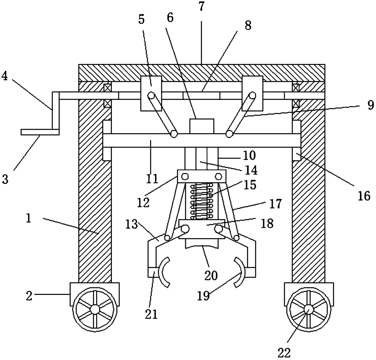
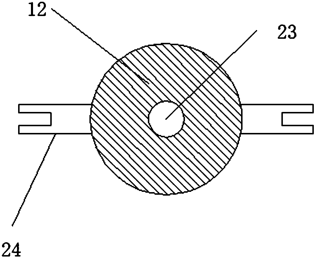
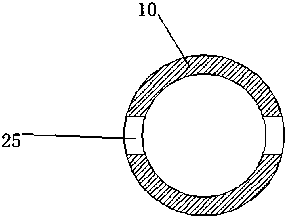
[0027] refer to Figure 1-5 , in an embodiment of the present invention, an installation and lifting device suitable for laying oil pipelines of different diameters includes a support frame 1, and a buffer pad 2 is installed at the lower end of the support frame 1 to reduce the shaking generated during the working process of the entire device. Universal wheels 22 are installed on the lower end of the buffer pad 2 to realize the movement of the whole device. A horizontal frame 7 is installed on the upper end of the support frame 1, and a guide block 5 is installed in the middle of the lower end of the horizontal frame 7. The guide block 5 includes a trapezoidal block 28 and slide block 29, the middle part of the lower end of the horizontal frame 7 is provided with a dovetail groove that cooperates with the trapezoidal block 28, so that the guide block 5 can move left and right along the horizontal frame, ensuring the straight line during the movement of the guide block 5 The middle part of the slider 29 is provided with a first threaded hole 30 cooperating with the screw rod 8, which is used to convert the linear motion of the screw rod 8 into the left and right linear motion of the guide block 5, and the middle part of the guide block 5 is equipped with a screw rod 8, the screw rod 8 left end is provided with left screw thread 26, and screw rod 8 right end is provided with right screw thread 27, and described screw rod 8 two ends are provided with the screw thread of different direction of rotation so that two guide blocks 5 move along the opposite direction, screw rod 8 left ends install There is a driving disc 4, and a driving handle 3 is installed on the left end of the driving disc 4, which is used to drive the driving disc 4 to rotate, so that the screw rod 8 rotates synchronously. The friction force between human hands, the lower end of the guide block 5 is hinged with the first pull rod 9, the lower end of the first pull rod 9 is equipped with a lifting plate 11, and the inner side of the support frame 1 is provided with a lifting groove 16 that cooperates with the lifting plate 11, It is used to guide the up and down movement of the lifting plate 11 and avoid the left and right shaking of the lifting plate 11. The middle part of the lower end of the lifting plate 11 is equipped with a fixed cylinder 10. The limit groove 25 is used to guide the up and down movement of the hinged rod 24, preventing the lifting block 12 from rotating together with the screw rod 14. The screw rod 14 is installed inside the fixed cylinder 10, and the upper end of the screw rod 14 is connected to Drive motor 6 is arranged, is used to drive screw mandrel 14 to rotate, and drive motor 6 is installed in the middle part of lifting plate 11 upper end, and screw mandrel 14 middle part is equipped with lifting block 12, and the middle part of described lifting block 12 is provided with screw mandrel 14 mutual cooperation. The second threaded hole 23 is used to convert the rotary motion of the screw rod 14 into the linear motion of the lifting block 12. The left and right ends of the lifting block 12 are equipped with hinged rods 24, and the outside of the hinged rods 24 is equipped with a second pull rod 17. The second pull rod The lower end of 17 is hinged with a clamping rod 13, a clamping block 21 is installed on the inner side of the clamping rod 13, a clamping ring 19 is installed on the inner side of the clamping block 21, a fixing block 18 is installed on the bottom of the fixing cylinder 10, and the fixing block 18 is installed on the inner side of the clamping block 21. 18 and the outside of the screw mandrel 14 between the lifting block 12 are covered with a buffer spring 15, which is used to buffer the up and down movement of the lifting block 12, and the middle part of the lower end of the fixed block 18 is equipped with a collision pad 20.
[0028] Said one is suitable for the installation and lifting device of oil pipelines of different diameters. When working, the whole device is driven by the universal wheel 22 to move back and forth. The rotating disk 4 drives the screw 8 to rotate, so that the two guide blocks 5 move to the middle of the screw 8, and then the lifting plate 11 drives the entire fixed cylinder 10 to move downward through the action of the pull rod 9, so that the oil pipeline to be transported It is located in the middle of the clamping ring 19. Afterwards, the drive motor 6 is started to drive the screw rod 14 to rotate, and then the lifting block 12 is driven to move downward, thereby driving the clamping rod 13 to move downward through the action of the pull rod 17, and then through The clamping ring 19 moves toward the middle of the oil pipeline, cooperates with the collision pad 20 to realize the clamping of the oil pipeline, and then reversely turns the driving handle 3, so that the lifting plate 11 moves upwards and drives the clamping ring 19 to clamp The live oil pipeline is moved up synchronously, and then the whole device is moved, and after the oil pipeline is transported to the installation site, the drive handle 3 is reversely turned again to make the oil pipeline move down, and at the same time, the drive motor 6 is reversely started to loosen the clamping ring 19. Open the oil pipeline, and then realize the lifting, handling and installation of the oil pipeline. The present invention has a reasonable structure and a novel design. Through the mutual cooperation between the provided clamping ring 19 and the interference pad 20, the lifting of oil pipelines with different diameters is realized, which not only effectively avoids the oil pipelines during the lifting process. Shaking left and right, the oil pipeline can be sent to the installation position in preparation, and at the same time, it also reduces the labor intensity of workers, meets the needs of oil pipeline laying, and has strong practicability.
[0029]The above descriptions are only preferred embodiments of the present invention, and are not intended to limit the present invention. Any modifications, equivalent replacements, improvements, etc. made within the spirit and principles of the present invention shall be included in the scope of the present invention. within the scope of protection.

PUM

no PUM

Description & Claims & Application Information

We can also present the details of the Description, Claims and Application information to help users get a comprehensive understanding of the technical details of the patent, such as background art, summary of invention, brief description of drawings, description of embodiments, and other original content. On the other hand, users can also determine the specific scope of protection of the technology through the list of claims; as well as understand the changes in the life cycle of the technology with the presentation of the patent timeline. Login to view more.

Similar technology patents

Laser beam coupling output device for high-power semiconductor

InactiveCN102012567AReasonable structureReduce the difficulty of machiningPolarising elementsSemiconductor laser theoryPower semiconductor device
Owner:BEIJING UNIV OF TECH

Classification and recommendation of technical efficacy words

  • Innovative design
  • Reasonable structure

Catheter with bendable tip

ActiveUS20090306650A1Innovative designElectrotherapyEar treatmentCatheter deviceBody cavity
Owner:BIOSENSE WEBSTER INC

Efficient broadband switching-mode amplifier

ActiveUS20050083122A1Innovative designPresent inventionPush-pull amplifiersPhase-splittersAudio power amplifierBroadband amplifiers
Owner:RAYTHEON CO

A ceramic insulator device for high voltage capacitor

InactiveCN101546636ALow manufacturing costReasonable structureSuspension/strain insulatorsHigh voltage capacitorsEngineering
Owner:王海龙
Why Eureka
Try Eureka