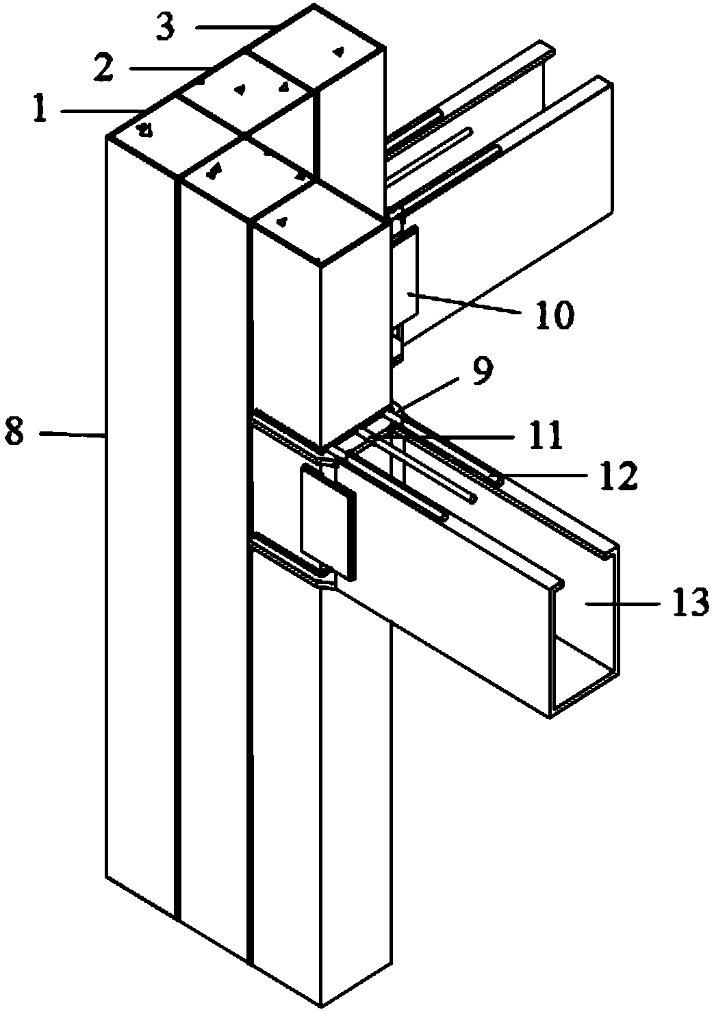
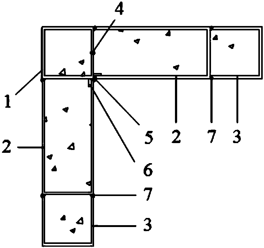
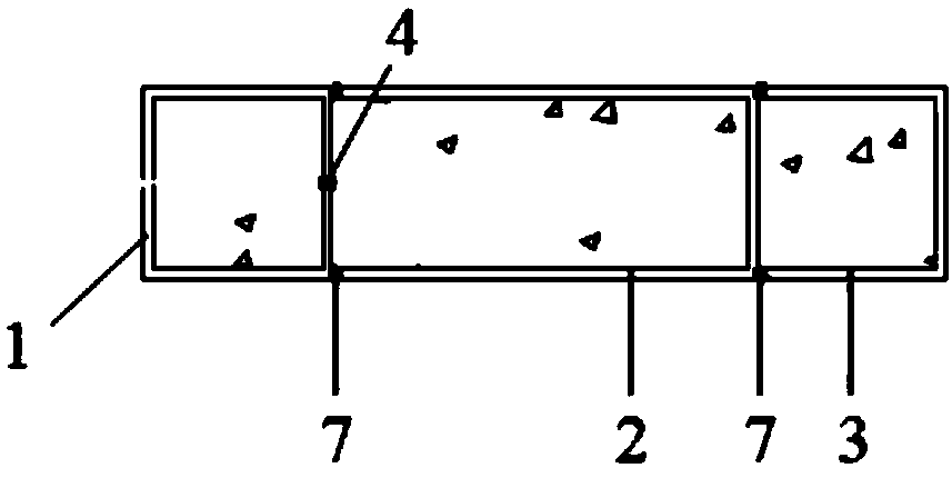
Rigid connection joint of cold-bending multi-cavity steel tube concrete special-shaped column and U-shaped combination beam
A technology of concrete-filled steel tube and rigid connection, which is applied in the direction of architecture and building structure, can solve the problems of reducing its own bearing capacity, the bearing capacity and ductility of special-shaped concrete-filled steel tube frame structure adverse effects, and reducing the concrete constraint effect of columns and joints, etc., to achieve Improve the anti-seismic performance, facilitate home placement, and improve the effect of indoor viewing
- Summary
- Abstract
- Description
- Claims
- Application Information
AI Technical Summary
Problems solved by technology
Method used
Image

Examples
Embodiment Construction
[0041] The present invention will be further described below in conjunction with the examples, but it should not be understood that the scope of the subject of the present invention is limited to the following examples. Without departing from the above-mentioned technical ideas of the present invention, various replacements and changes made according to common technical knowledge and conventional means in this field shall be included in the protection scope of the present invention.
[0042] The rigid connection node of the cold-formed multi-cavity steel pipe concrete special-shaped column and the U-shaped composite beam, its processing technology includes the following steps:
[0043] 1) Cut out a rectangular thin-walled steel plate, and bend it into a hollow steel pipe with a rectangular cross-section by cold bending. The selected cross-section is perpendicular to the length direction of the hollow steel pipe, and the preferred cross-section in this embodiment is a square. ...
PUM
 Abstract
Description
Claims
Application Information