Improved type convenient wall face brushing device

A convenient and improved technology, applied in construction, building structure and other directions, can solve the problems of inconvenient movement and handling, difficult disassembly and maintenance, time-consuming and labor-intensive, etc., and achieves the effect of convenient operation and simple structure.

Inactive Publication Date: 2018-06-01
广州猎狗信息咨询有限公司
View PDF0 Cites 2 Cited by
  • Summary
  • Abstract
  • Description
  • Claims
  • Application Information

AI Technical Summary

Problems solved by technology

The structure of the existing wall brush is basically that the front end of the handle is provided with a bracket, the front end of the bracket is provided with a cross bar, and the cross bar is provided with rollers. This kind of wall brush is inconvenient in use, for example, when the brush position is relatively high. , the operator is used to connecting a long rod to the lower end of the handle, which is not only time-consuming and laborious, but also has a poor brushing effect, and it is easy to cause a large difference in the effect after brushing, and the quality of the wall is uneven. In addition, the existing mechanical brush The structure of the wall equipment is complex, difficult to disassemble and maintain, expensive, and the overall volume is large, which makes it inconvenient to move and carry. At the same time, there are problems of poor control flexibility and stability

Method used


Image

  • Improved type convenient wall face brushing device
  • Improved type convenient wall face brushing device
  • Improved type convenient wall face brushing device

Examples


Embodiment Construction

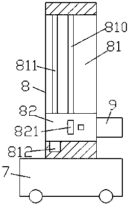
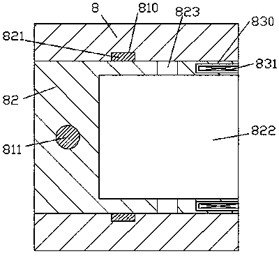
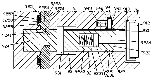
[0015] Such as figure 1 , figure 2 and image 3 As shown, an improved portable wall painting device of the present invention includes a loading car body 7, a lifting drive body 8 fixed in the loading car body 7, and a painting body 9, which is characterized in that: The lifting drive body 8 is provided with a lifting chute 81, and the inner walls of the front and rear sides of the lifting chute 81 are symmetrically provided with guide chute 810 extending up and down. Frame slider 82, the front and rear sides of the mounting frame slider 82 are respectively fixed with guide sliders 821 extending into the guide chute 810 on the front and rear sides and are slidably connected, and the mounting frame slides The block 82 is provided with an installation groove 822 in the right side end surface, and the described painting machine body 9 is slidably connected with the installation groove 822, and the installation frame slider 82 on the left side of the installation groove 822 is ...


PUM


Abstract

The invention discloses an improved type convenient wall face brushing device. The improved type convenient wall face brushing device comprises a loading car body, a lifting driving machine body fixedto the interior of the loading car body and a brushing machine body. A lifting sliding groove is formed in the lifting driving machine body, guiding sliding grooves formed to extend up and down are symmetrically formed in the inner walls of the front side and the rear side of the lifting sliding groove, a mounting frame sliding block is slidably connected with the interior of the lifting slidinggroove in a matched mode, guiding sliding blocks extending into the guiding sliding grooves on the front side and the rear side are fixedly arranged on the front side end face and the rear side end face of the mounting frame sliding block correspondingly, and the guiding sliding blocks are slidably connected with the mounting frame sliding block in a matched mode. A mounting groove is formed in the right side end face of the mounting frame sliding block, the brushing machine body is slidably connected with the mounting groove in a matched mode, a lifting driving mechanism is arranged in the mounting frame sliding block on the left side of the mounting groove, and locking holes are symmetrically formed in the inner walls of the front side and the rear side of the mounting groove. The improved type convenient wall surface brushing device is simple in structure, can achieve adjusting work of automatic inward extending and outward extending of a roller brush and automatic locking and unlocking work of a locking execution mechanism, and is convenient to dismount, mount and maintain.

Description

technical field [0001] The invention relates to the technical field of building decoration machinery, in particular to an improved portable wall painting device. Background technique [0002] With the further development of reform and opening up, people's living standards have been further improved. People pay more and more attention to the quality of the house, and wall painting is the most basic and important link. The structure of the existing wall brush is basically that the front end of the handle is provided with a bracket, the front end of the bracket is provided with a cross bar, and the cross bar is provided with rollers. This kind of wall brush is inconvenient in use, for example, when the brush position is relatively high. , the operator is used to connecting a long rod to the lower end of the handle, which is not only time-consuming and laborious, but also has a poor brushing effect, and it is easy to cause a large difference in the effect after brushing, and th...

Claims


Application Information

Patent Timeline
Patent Type & Authority Applications(China)
IPC IPC(8): E04F21/08
CPCE04F21/08
Inventor 叶翠颖
Owner 广州猎狗信息咨询有限公司
Why Eureka
Try Eureka