Crosswind sprinkling type condenser

A condenser and shower type technology, which is applied in the field of side-wind shower type condensers, can solve the problems of low heat exchange efficiency and high energy consumption, and achieve the effect of saving energy and improving heat dissipation effect.

Pending Publication Date: 2018-06-01
江苏开来医药科技有限公司
0 Cites 0 Cited by

AI-Extracted Technical Summary

Problems solved by technology

[0003] In order to improve the condensation effect, there are now shower condensers, but in this way, the temperature of the water collecte...

Abstract

The invention belongs to the technical field of condensers, and particularly relates to a crosswind sprinkling type condenser. A spray tower comprises a side wall. The side wall is of a sandwich structure composed of an inner wall and an outer wall, and an intermediate sandwich is arranged in the side wall and connected with a water inlet pipe at the top. The intermediate sandwich is used as a water channel. A spray space is formed in the spray tower. The water inlet pipe is connected with a water collection tank through a return pipe. A plurality of small holes are formed in the inner wall. The water collection tank is mounted under a condenser main body and the spray tower. A fan is mounted on one side of the condenser main body. According to the crosswind sprinkling type condenser, reused spray water enters the spray tower for continuous cooling, water is sprayed into the spray space from spray heads of the inner wall of the spray tower, then falls to the condenser main body at thebottom and takes absorbed heat away, part of water is evaporated and blown away rapidly from one side of the fan, part of heat is taken away, remaining water falls to the water collection tank for recycle, the cooling effect is improved, and energy resources are saved.

Application Domain

Evaporators/condensersTrickle coolers

Technology Topic

Spray towerPiping +8

Image

  • Crosswind sprinkling type condenser

Examples

  • Experimental program(1)

Example Embodiment

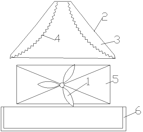
[0013] The specific implementation of the present invention will be described in conjunction with the examples.
[0014] like figure 1 As shown, the side wind shower condenser includes a condenser main body 5, a fan 1, a water collection tank 6, and a spray tower 2. The spray tower 2 includes a side wall, and the side wall is composed of an inner wall and an outer wall. Structure, the interior is a middle interlayer 3, and the middle interlayer 3 is connected to the water inlet pipe at the top; the middle interlayer 3 is a water flow channel, and when water passes through the water flow channel, it can dissipate heat through the outer wall. The inside of the spray tower 2 is a spray space; the water inlet pipe is connected to the sump 6 through a return line, and a water level sensor and a water supply valve are installed in the sump 6, and the water supply valve is connected to the water supply pipeline, and the water level sensor The controller controls the water replenishment valve to open.
[0015] The inner wall is provided with a plurality of water outlet holes 4, and the water outlet holes 4 face the spray space inside the spray tower 2, and the condenser main body 5 is installed below the spray space of the spray tower 2; The water collecting tank 6 is installed under the condenser main body 5 and the spray tower 2, and the fan 1 is installed on one side of the condenser main body 5. After the water drips out from the water outlet hole 4, it falls onto the condenser main body 5, part of the water evaporates, and is blown on one side by the fan 1, so that the water vapor is blown away from the condenser main body 5 as soon as possible.
[0016] The outer wall of the spray tower 2 is a truncated conical structure, and the inner wall protrudes toward the spray space; the top of the spray tower 2 is a circular air vent, and the lower end is a circular shower outlet, and the inner diameter of the air vent is less than The inner diameter of the shower outlet; the condenser main body 5 is installed below the shower outlet. The convex inner wall can increase the water spraying area and increase the density of water droplets. The convex inner wall can also increase the thickness of the intermediate interlayer 3, and can accommodate more recycled water. The recycled water can be further radiated and cooled in the intermediate interlayer 3 through the heat-conducting inner and outer walls.
[0017] And the spray tower 2 has a vent here, and the water vapor generated after absorbing heat on the condenser main body 5 partially enters the spray tower 2 and can be discharged from the vent.
[0018] Each of the water outlet holes 4 is perpendicular to the tangent plane of the inner wall of the spray tower 2 where it is located. The small hole 4 of the water outlet can discharge water more evenly and spray in different directions to ensure that there is spray water in the entire spray space.

PUM

no PUM

Description & Claims & Application Information

We can also present the details of the Description, Claims and Application information to help users get a comprehensive understanding of the technical details of the patent, such as background art, summary of invention, brief description of drawings, description of embodiments, and other original content. On the other hand, users can also determine the specific scope of protection of the technology through the list of claims; as well as understand the changes in the life cycle of the technology with the presentation of the patent timeline. Login to view more.

Similar technology patents

High-efficiency heat dissipation motor

Owner:陕西易盈电气科技工业有限公司

Heat radiator

Owner:INNOCOM TECH SHENZHEN +1

Computer host apparatus

InactiveCN105353843AImprove cooling effectImprove operating performance
Owner:TIANJIN ZHONGYUN TECH CO LTD

Classification and recommendation of technical efficacy words

  • Improve cooling effect
  • Energy saving

Backlight unit

InactiveCN103336388AImprove cooling effecteven heat distribution
Owner:TCL CHINA STAR OPTOELECTRONICS TECH CO LTD

Data center and cooling system thereof

Owner:HONGFUJIN PRECISION ELECTRONICS (TIANJIN) CO LTD

Photovoltaic cleaning robot

InactiveCN104984942AEnergy savingeasy to use
Owner:上海联星股权投资管理有限公司
Why Eureka
Try Eureka