
Temperature transmitter

A temperature transmitter and temperature sensor technology, applied in the direction of thermometers, thermometer parts, instruments, etc., can solve the problems of inability to achieve multiple signal access, troublesome debugging, temperature deviation or beating, etc., to avoid failure to be online The effect of convenient scheduling and post-debugging work and simple structure

Pending Publication Date: 2018-06-01
SHUNCHANG COUNTY HONGRUN PRECISION INSTR
View PDF0 Cites 1 Cited by
  • Summary
  • Abstract
  • Description
  • Claims
  • Application Information

AI Technical Summary

Problems solved by technology

Most of the temperature sensor and the temperature transmitter fixed on the top work in a high temperature environment, and it is generally difficult for the operator to approach, which brings great trouble to the later debugging work, and most of the existing temperature transmitters use a temperature sensor However, the bridge sampling circuit is not related to other signal sampling circuits. Therefore, the bridge sampling circuit of the temperature transmitter cannot realize the access of multiple signals, and the signal that can be accessed is single. In addition, the input The temperature signal of the temperature transmitter is easily interfered by industrial strong electricity, which will eventually cause deviation or jump in the measured temperature

Method used


Image

  • Temperature transmitter
  • Temperature transmitter

Examples


Embodiment Construction

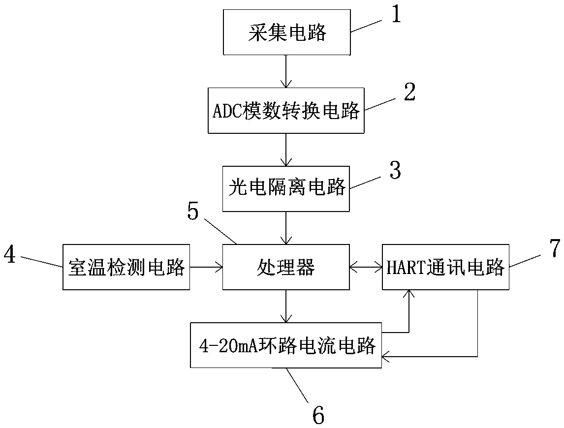
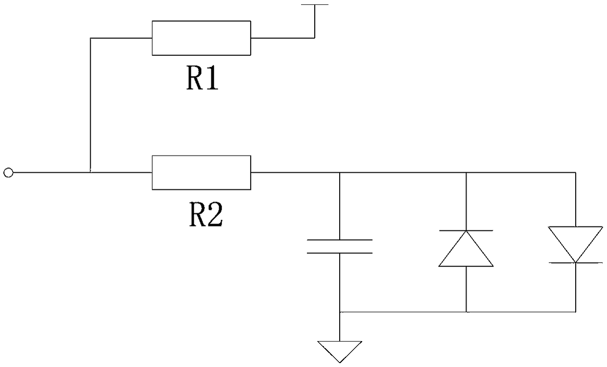
[0019] The specific implementation of the temperature transmitter of the present invention will be described in detail below in conjunction with the accompanying drawings. Such as figure 1 with figure 2 As shown, a temperature transmitter includes an acquisition circuit 1, an ADC analog-to-digital conversion circuit 2, a photoelectric isolation circuit 3, a room temperature detection circuit 4, a processor 5, a 4-20mA loop current circuit 6 and a HART communication circuit 7, The acquisition circuit 1 is a voltage-dividing acquisition circuit. The acquisition circuit 1 includes a temperature sensor R1 and a grounding resistor R2 connected in series. The free end of the temperature sensor R1 is connected to a fixed voltage, and the voltage at the middle point between the temperature sensor R1 and the grounding resistor R2 is used as the voltage of the acquisition circuit 1. The output voltage, the acquisition circuit 1 is sequentially connected with the ADC analog-to-digital ...


PUM


Abstract

The invention discloses a temperature transmitter comprising an acquisition circuit, an ADC analog-to-digital conversion circuit, a photoelectric isolation circuit, a room temperature detection circuit, a processor, a 4-20mA loop current circuit and a HART communication circuit. The acquisition circuit is in communication connection with the ADC analog-to-digital conversion circuit and the photoelectric isolation circuit in turn. The photoelectric isolation circuit, the room temperature detection circuit and the 4-20mA loop current circuit are in communication connection with the processor. The HART communication circuit and the processor are in two-way communication connection. The 4-20mA loop current circuit is also connected with the HART communication circuit to form a circuit loop. The temperature transmitter can support the access of more signals, can realize remote debugging, and has strong anti-interference ability.

Description

technical field [0001] The invention relates to the field of collection, transmission and output of industrial data, in particular to a temperature transmitter. Background technique [0002] As a temperature signal conversion instrument, the temperature transmitter is installed in the primary instrument case on the top of the temperature sensor. It is mainly used to receive the temperature signal collected by the temperature sensor and convert the temperature signal collected by the temperature sensor into a standard analog signal such as 4 -20mA signal. Most of the temperature sensor and the temperature transmitter fixed on the top work in a high temperature environment, and it is generally difficult for the operator to approach, which brings great trouble to the later debugging work, and most of the existing temperature transmitters use a temperature sensor However, the bridge sampling circuit is not related to other signal sampling circuits. Therefore, the bridge samplin...

Claims


Application Information

Patent Timeline
Patent Type & Authority Applications(China)
IPC IPC(8): G01K1/00
CPCG01K1/00G01K2219/00
Inventor 林善平魏小东陈志扬梁建
Owner SHUNCHANG COUNTY HONGRUN PRECISION INSTR
Learn More