Synchronous rectification control circuit, control device and switching power supply of switching power supply
A technology of synchronous rectification and control circuit, which is applied in the direction of output power conversion device, control/regulation system, high-efficiency power electronic conversion, etc. It can solve the problems of complex structure of adjusting resistance circuit and limitation of circuit topology, and achieve convenient and flexible configuration, Easy to integrate design and prevent false triggering effects
- Summary
- Abstract
- Description
- Claims
- Application Information
AI Technical Summary
Problems solved by technology
Method used
Image

Examples
Embodiment 1
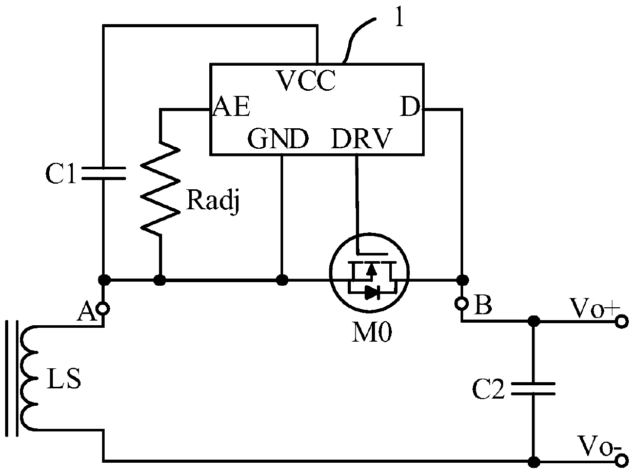
[0055] Such as Figure 2-3 As shown, the synchronous rectification control device of the switching power supply involved in this embodiment includes a transformer output winding LS, an output capacitor C2, an adjustment resistor Radj, a bypass capacitor C1, a synchronous rectification tube M0 and a synchronous rectification control circuit 1, wherein the adjustment resistor One end of Radj is connected to the time setting end AE of the synchronous rectification control circuit 1, one end of the bypass capacitor C1 is connected to the power supply end VCC of the synchronous rectification control circuit 1, and the gate of the synchronous rectification tube M0 is connected to the drive end of the synchronous rectification control circuit 1 DRV connection, the drain of the synchronous rectifier M0 is connected to the drain terminal D of the synchronous rectification control circuit 1, the source of the synchronous rectifier M0, the other end of the adjustment resistor Radj, the ot...
Embodiment 2
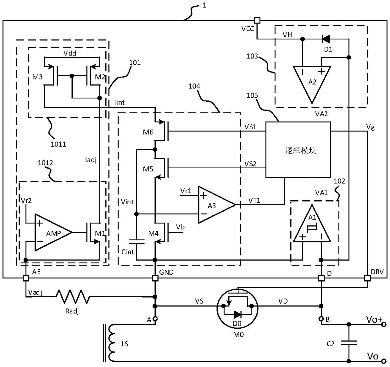
[0085] Such as Figure 4 As shown, the synchronous rectification control circuit and control device of the switching power supply involved in this embodiment are basically the same as those of Embodiment 1, the difference is that in the synchronous rectification control circuit 1, the resistance between the integral current Iint and the adjustment resistor Radj In this way, the voltage of adjusting resistor Radj can be detected by controlling the current flowing through adjusting resistor Radj, so that the integral current Iint is proportional to adjusting resistor Radj.
[0086] Specifically, the regulating current generating unit 1012 is used to generate the integral current Iint according to the reference current Iref, that is, in a specific implementation, the regulating current generating unit 1012 also includes a reference resistor Rref, and the non-inverting input terminal of the amplifier AMP is connected to one end of the regulating resistor Radj, The inverting input ...
Embodiment 3
[0088] Such as Figure 5 As shown, the synchronous rectification control device of the switching power supply involved in this embodiment is based on the synchronous rectification control circuit 1 in embodiment 1 or embodiment 2. In view of the synchronous rectification control circuit 1 and the adjustment resistor Radj and the synchronous rectification tube M0, etc. A 2-port structure (such as points A and B in the figure) is effectively formed to provide a synchronous rectification control device for a switching power supply. Specifically, one end of the transformer output winding LS is connected to one end of the output capacitor C2 as described The output positive terminal Vo+ of the switching power supply; the other end of the transformer output winding LS is connected to the drain of the synchronous rectifier M0, and the other end of the output capacitor C2 is connected to the reference ground GND of the synchronous rectification control circuit 1 as the output of the sw...
PUM
 Abstract
Description
Claims
Application Information
 - R&D
- Intellectual Property
- Life Sciences
- Materials
- Tech Scout
- Unparalleled Data Quality
- Higher Quality Content
- 60% Fewer Hallucinations
Browse by: Latest US Patents, China's latest patents, Technical Efficacy Thesaurus, Application Domain, Technology Topic, Popular Technical Reports.
© 2025 PatSnap. All rights reserved.Legal|Privacy policy|Modern Slavery Act Transparency Statement|Sitemap|About US| Contact US: help@patsnap.com