Ultra-wideband miniaturized radio frequency module

A radio frequency component and ultra-wideband technology, applied in the field of ultra-wideband miniaturized radio frequency components, can solve the problems of poor anti-interference performance, large size, noise, etc., and achieve high gain flatness, low noise figure, and low noise figure.

Inactive Publication Date: 2018-06-01
BEIJING INST OF REMOTE SENSING EQUIP
View PDF4 Cites 12 Cited by
  • Summary
  • Abstract
  • Description
  • Claims
  • Application Information

AI Technical Summary

Problems solved by technology

[0003] The purpose of the present invention is to provide an ultra-wideband miniaturized radio frequency component to solve the problems of noise, gain flatness, poor anti-interference performance and large volume of the previous radio frequency components within the ultra-wideband bandwidth

Method used


Image

  • Ultra-wideband miniaturized radio frequency module

Examples


Embodiment Construction

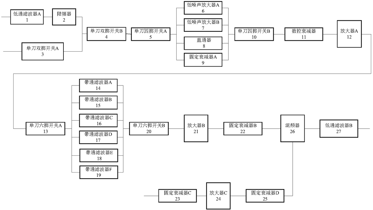
[0015] An ultra-broadband miniaturized radio frequency component, comprising: a low-pass filter A1, a limiter 2, a single-pole double-throw switch A3, a single-pole double-throw switch B4, a single-pole four-throw switch A5, a single-pole four-throw switch B10, and a digitally controlled attenuator 11 , amplifier A12, single-pole six-throw switch A13, single-pole six-throw switch B20, amplifier B21, fixed attenuator B22, fixed attenuator C23, amplifier C24, fixed attenuator D25, mixer 26 and low-pass filter B27, also includes : LNA A6, LNA B7, pass-through 8, fixed attenuator A9, band-pass filter A14, band-pass filter B15, band-pass filter C16, band-pass filter D17, band-pass filter E18 and Bandpass filter F19.

[0016] The input terminal of the ultra-wideband miniaturized radio frequency component inputting the microwave signal is connected to the input terminal of the low-pass filter A1, the output terminal of the low-pass filter A1 is connected to the input terminal of the ...


PUM


Abstract

The invention discloses an ultra-wideband miniaturized radio frequency module. An input signal passing a low pass filter A (1) and a limiter (2) and a calibration signal passing a single knife doublethrow switch A (3) are selected by a single knife double throw switch B (4), and then selected through a single knife four throw switch A (5); then power control is performed through a low noise amplifier A (6), a low noise amplifier B (7), a direct connector (8) and one of the four ways of a fixed attenuator; then power adjustment is performed through a single knife four throw switch B (10), a numerical attenuator (11) and an amplifier A (12); then selection is carried out by a single knife six throw switch A (13), and frequency selection is carried out through one of the six ways of a band-pass filter; and a local oscillator signal passes a mixer (26) and a low pass filter B (27) to obtain an intermediate frequency signal. The ultra-wideband miniaturized radio frequency module solves theproblems of the ultra-wideband low noise design, the gain flatness control, the anti-interference and the miniaturization.

Description

technical field [0001] The invention relates to a radio frequency component, in particular to an ultra-wideband miniaturized radio frequency component. Background technique [0002] In the past, RF components consisted of limiters, microwave switches, attenuators, mixers, filters, power splitters and amplifiers, etc. After microwave signals were received through the main channel or calibration channel, they were selected by a single-pole double-throw switch and then fed into the The channel expands the dynamics through the attenuator after limiting the protection, enters the mixing frequency after amplification and filtering, and obtains the intermediate frequency signal after the mixing amplification and filtering. Because the frequency band is too wide, the number and types of components required are huge, which affects the performance of components. And because of the high process requirements, the integration is poor, the receiving bandwidth cannot be very wide, the nois...

Claims


Application Information

Patent Timeline
Patent Type & Authority Applications(China)
IPC IPC(8): H04B1/40
CPCH04B1/40
Inventor 刘腾达凡守涛
Owner BEIJING INST OF REMOTE SENSING EQUIP
Why Eureka
Try Eureka