
Laser electrochemical combined machining device with dual flow channels

A composite processing and electrochemical technology, applied in laser welding equipment, metal processing equipment, manufacturing tools, etc., can solve the problems of lack of recovery device, damage to the surface to be processed, easy accumulation around the laser spot, etc., and achieve the accuracy of eliminating chemical corrosion Not enough, the effect of accelerating the corrosion rate

Inactive Publication Date: 2018-06-05
QINGDAO TECHNOLOGICAL UNIVERSITY
View PDF7 Cites 2 Cited by
  • Summary
  • Abstract
  • Description
  • Claims
  • Application Information

AI Technical Summary

Problems solved by technology

However, during processing, slag and debris tend to accumulate around the laser spot, forming a "crater"
The laser electrochemical composite processing can eliminate slag and debris, but the chemical liquid nozzle in the prior art is open, lacks an effective recovery device, the chemical liquid will flow and spread to other areas of the device to be processed, and damage the surface to be processed. At the same time, the non-precision design of the chemical liquid nozzle and the electrode will enlarge the laser etching aperture and make it difficult to improve the processing accuracy.

Method used


Image

  • Laser electrochemical combined machining device with dual flow channels
  • Laser electrochemical combined machining device with dual flow channels
  • Laser electrochemical combined machining device with dual flow channels

Examples


Embodiment Construction

[0022] The present invention will be further described below in conjunction with the accompanying drawings and embodiments.

[0023] It should be pointed out that the following detailed description is exemplary and intended to provide further explanation to the present application. Unless defined otherwise, all technical and scientific terms used herein have the same meaning as commonly understood by one of ordinary skill in the art to which this application belongs.

[0024] It should be noted that the terminology used here is only for describing specific implementations, and is not intended to limit the exemplary implementations according to the present application. As used herein, unless the context clearly dictates otherwise, the singular is intended to include the plural, and it should also be understood that when the terms "comprising" and / or "comprising" are used in this specification, they mean There are features, steps, operations, means, components and / or combinatio...


PUM


Abstract

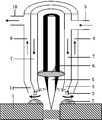
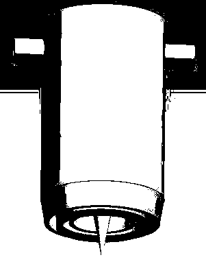
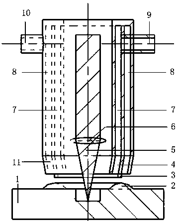
The invention discloses a laser electrochemical combined machining device with dual flow channels. The device comprises an optical lens, the inner annular flow channel, the outer annular flow channel,a through hole of the inner annular flow channel, a through hole of the outer annular flow channel, an annular electrode, an inner ring opening and an outer ring opening. The optical lens is locatedon the inner side of the inner annular flow channel, the inner annular flow channel is located on the inner side of the outer annular flow channel, the through hole of the inner annular flow channel is communicated with the inner annular flow channel, the through hole of the outer annular flow channel is communicated with the outer annular flow channel, the inner ring opening is communicated withthe inner annular flow channel, and the outer ring opening is communicated with the outer annular flow channel. The inner annular flow channel and the outer annular flow channel are used for conveyingchemical liquid for corroding slag and fragments stacked in the laser machining process; the annular electrode is located between the inner ring opening and the outer ring opening, and the potentialdifference exists between the annular electrode and a device to be machined. By adopting the unique design of the dual annular flow channels and the annular electrode, the application range of the chemical liquid is controlled, and the defects that a volcanic vent exists in the existing laser machining process, and the chemical corrosion precision is not good enough are eliminated.

Description

technical field [0001] The invention relates to a laser electrochemical compound processing device with double channels. Background technique [0002] Laser processing is a green and efficient advanced manufacturing technology, which is widely used because of its unique advantages. However, during processing, slag and debris tend to accumulate around the laser spot, forming a "crater". Laser electrochemical composite processing can eliminate slag and debris, but the chemical liquid nozzle in the prior art is open, lacks an effective recovery device, and the chemical liquid will flow and spread to other areas of the device to be processed, damaging the surface to be processed, At the same time, the non-precision design of the chemical liquid nozzle and the electrode will enlarge the laser etching aperture, making it difficult to improve the processing accuracy. Contents of the invention [0003] In order to solve the above problems, the present invention proposes a laser ...

Claims


Application Information

Patent Timeline
Patent Type & Authority Applications(China)
IPC IPC(8): B23H5/06B23K26/00
CPCB23H5/06B23K26/0093
Inventor 孙树峰邵晶王永武韩素立王克楠张华峰
Owner QINGDAO TECHNOLOGICAL UNIVERSITY
Learn More