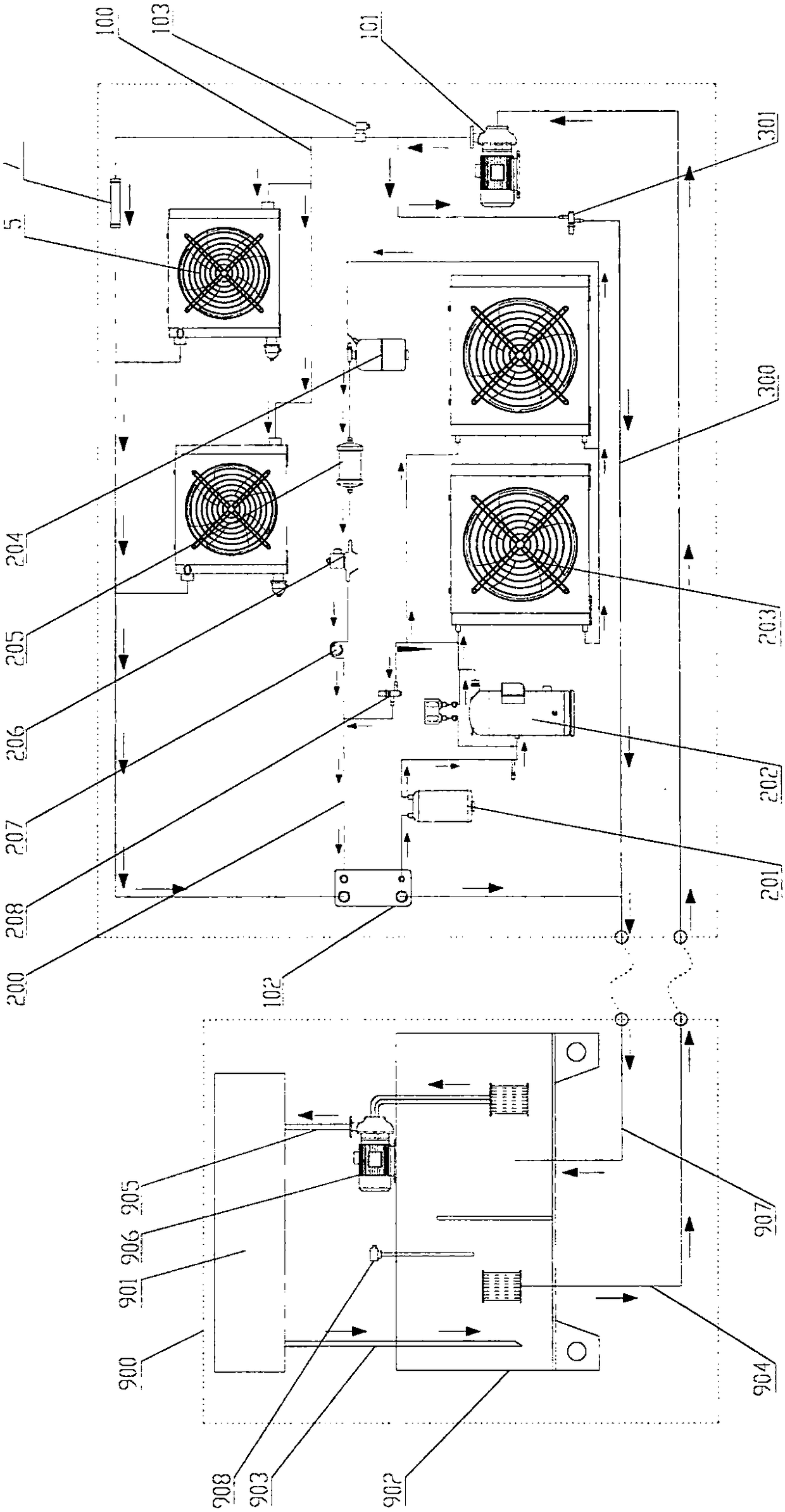
Industrial constant temperature device of hydraulic bypass with adjustable type pressure relief valve
A technology of constant temperature device and pressure relief valve, which is applied in the direction of fluid pressure actuation device, temperature control, servo meter circuit, etc., which can solve the problems of easy damage, scrapping, unbalanced flow, exceeding the radiator, etc., and extend the use of the radiator Longevity, guaranteed stable operation, and energy-saving effects
- Summary
- Abstract
- Description
- Claims
- Application Information
AI Technical Summary
Problems solved by technology
Method used
Image
Examples
Embodiment 1
[0092] Example 1. When the liquid flows from left to right and the main hydraulic circuit is blocked, the pressure at the left end of the adjustable pressure relief valve is greater than the pressure at the right end, because the pressure in the fluid channel of the piston on the left side of the diaphragm is greater than that of the piston on the right side of the diaphragm The pressure in the fluid channel, the fluid pushes the diaphragm to move to the right, so that the piston also moves to the right. The piston fluid channel flows out through the fluid hole to a fluid channel half cavity on the right, and then flows into the right piston fluid channel, so as to achieve the purpose of pressure relief. At this time, the spring on the left is in a stretched state. The spring on the right is in a compressed state until the pressure on the left and right sides of the diaphragm is equal, the piston returns to its original position, and the main hydraulic circuit returns unobstruc...
Embodiment 2
[0093] Example 2. When the liquid flows from left to right and the main hydraulic circuit is blocked, the pressure at the right end of the adjustable pressure relief valve is greater than the pressure at the left end, because the pressure in the fluid channel of the piston on the right side of the partition is greater than that of the piston on the left side of the partition The pressure in the fluid channel, the fluid pushes the diaphragm to move to the left, so that the piston also moves to the left. The piston fluid channel flows out through the fluid hole to a fluid channel half cavity on the left, and then flows into the left piston fluid channel, so as to achieve the purpose of pressure relief. At this time, the spring on the right is in a stretched state. The spring on the left side is in a compressed state until the pressure on the left side and the right side of the diaphragm are equal, and the main hydraulic circuit returns unobstructed.
[0094] The radiator 5 is an...
Embodiment 1
[0096] The accumulator tube is built in. When the liquid inlet and outlet of the anti-impact energy storage radiator are located on the top of the first liquid collection tank 501 and the second liquid collection tank 502, the energy storage tube 500 is installed in the first liquid collection tank 501 and the second liquid collection tank 502. The inside of the second sump 502 is enough.
PUM
 Abstract
Description
Claims
Application Information
 - R&D
- Intellectual Property
- Life Sciences
- Materials
- Tech Scout
- Unparalleled Data Quality
- Higher Quality Content
- 60% Fewer Hallucinations
Browse by: Latest US Patents, China's latest patents, Technical Efficacy Thesaurus, Application Domain, Technology Topic, Popular Technical Reports.
© 2025 PatSnap. All rights reserved.Legal|Privacy policy|Modern Slavery Act Transparency Statement|Sitemap|About US| Contact US: help@patsnap.com


