
Dynamic deflection instrument calibration method

A calibration method and the technology of the deflection meter, which are applied in the direction of instruments, measuring devices, and electrical devices, etc., can solve the problems of traceability and inability to give the indication value of the dynamic deflection meter

Active Publication Date: 2018-06-05
GUANGZHOU GRG METROLOGY & TEST CO LTD +1
View PDF6 Cites 0 Cited by
  • Summary
  • Abstract
  • Description
  • Claims
  • Application Information

AI Technical Summary

Problems solved by technology

[0005] In order to overcome at least one defect described in the above-mentioned prior art, the present invention provides a dynamic deflection meter calibration method, solves the problem of how to dynamically calibrate the dynamic deflection meter, and solves the problem that the traditional static calibration cannot be given in a certain Traceability of the indication value of the dynamic pendulum instrument under the rotating speed

Method used


Image

  • Dynamic deflection instrument calibration method
  • Dynamic deflection instrument calibration method
  • Dynamic deflection instrument calibration method

Examples


Embodiment

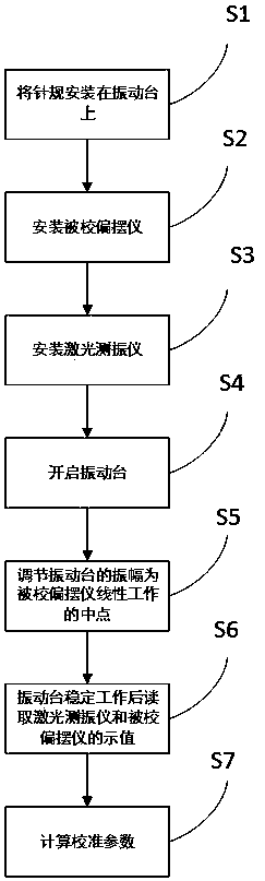
[0038] Such as figure 1 As shown, a dynamic deflection meter calibration method includes the following steps:

[0039] S1: Install the gauge on the vibration table;

[0040] S2: Install the pendulum to be calibrated;

[0041] S3: install the laser vibrometer;

[0042] S4: Turn on the vibration table;

[0043] S5: Adjust the amplitude of the vibrating table to the midpoint of the linear work of the pendulum to be corrected;

[0044] S6: Read the indications of the laser vibrometer and the calibrated pendulum after the vibration table works stably;

[0045] S7: Calculating calibration parameters.

[0046] In this embodiment, install through steps S1-S3:

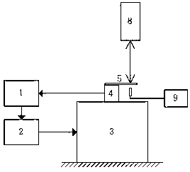
[0047] Wherein, in step S1, the standard needle gauge is installed on the installation platform that is located on the standard vibration table, and the standard needle gauge is installed to the appropriate position of the deflection meter measurement.


PUM


Abstract

The invention relates to the field of instrument calibration, and particularly to a dynamic deflection instrument calibration method. The method comprises the following steps of S1, mounting a gauge on a vibration platform; S2, mounting a calibrated deflection instrument; S3, mounting a laser vibration measuring instrument; S4, starting the vibration platform; S5, adjusting the vibration amplitudeof the vibration platform to the midpoint of linear operation of the calibrated deflection instrument; S6, after stable operation of the vibration platform, reading the indicated values of the laservibration measuring instrument and the calibrated deflection instrument; and S7, calculating a calibration parameter. The dynamic deflection instrument calibration method settles problems of dynamic calibration to the dynamic deflection instrument and incapability of tracing the indicated value of the dynamic deflection instrument in a certain rotating speed in traditional static calibration.

Description

technical field [0001] The present invention relates to the field of instrument calibration, and more specifically, relates to a method for calibrating a dynamic deflector. Background technique [0002] The rotation accuracy of the machine tool spindle is an important index to measure the performance of the mechanical system and one of the main factors affecting the working accuracy of the machine tool. In the drilling process of the PCB printed circuit board industry, 10%-15% of scrap and defective products are caused by the dynamic deflection of the spindle of the PCB drilling machine tool, so it is necessary to monitor the deflection of the spindle in real time. The dynamic yaw of the spindle is to measure the radial runout when the spindle is running at the working speed. By measuring the radial runout on the surface of the spindle, we can know whether the spindle is running normally and whether to do spindle maintenance. This is the same as that measured by a dial indic...

Claims


Application Information

Patent Timeline
IPC IPC(8): G01B11/02G01B7/02
CPCG01B7/02G01B11/02
Inventor 赵莹刘荣恩谢才智李建征叶凌华
Owner GUANGZHOU GRG METROLOGY & TEST CO LTD
Features
  • Generate Ideas
  • Intellectual Property
  • Life Sciences
  • Materials
  • Tech Scout
  • Unparalleled Data Quality
  • Higher Quality Content
  • 60% Fewer Hallucinations
Learn More