
Micro-seismic positioning system for networked multilayer orthogonal array

A positioning system and orthogonal array technology are applied in the field of networked multi-layer orthogonal array microseismic positioning systems, which can solve the problems of multi-target aliasing, unable to guarantee complete data measurement in all weather and all day, and large labor consumption. Achieve the effect of meeting the requirements of projectile landing point detection, reducing the probability of being destroyed by projectiles, and reducing construction costs

Pending Publication Date: 2018-06-05
成都中欣科创声学科技有限公司
View PDF0 Cites 3 Cited by
  • Summary
  • Abstract
  • Description
  • Claims
  • Application Information

AI Technical Summary

Problems solved by technology

The traditional method of manual target reporting is to judge the position of the projectile by using optical measurement methods such as manual on-site observation or telescopes after the projectile lands and explodes. The timeliness is poor, the manpower consumption is large, the accuracy is poor, and the efficiency is low, which can no longer meet the needs of training in the information age. The actual needs of target shooting; at present, the target reporting method has developed into an automatic target reporting method that uses a single optical, radar, acoustic and vibration or a combination of several methods. , The monitoring environment is relatively complex, multi-target aliasing is serious, etc. Traditional and modern methods still cannot guarantee that complete data can be measured all-weather and all-weather, and there are phenomena such as inaccurate target reporting data and loss of monitoring data.

Method used


Image

  • Micro-seismic positioning system for networked multilayer orthogonal array

Examples


Embodiment

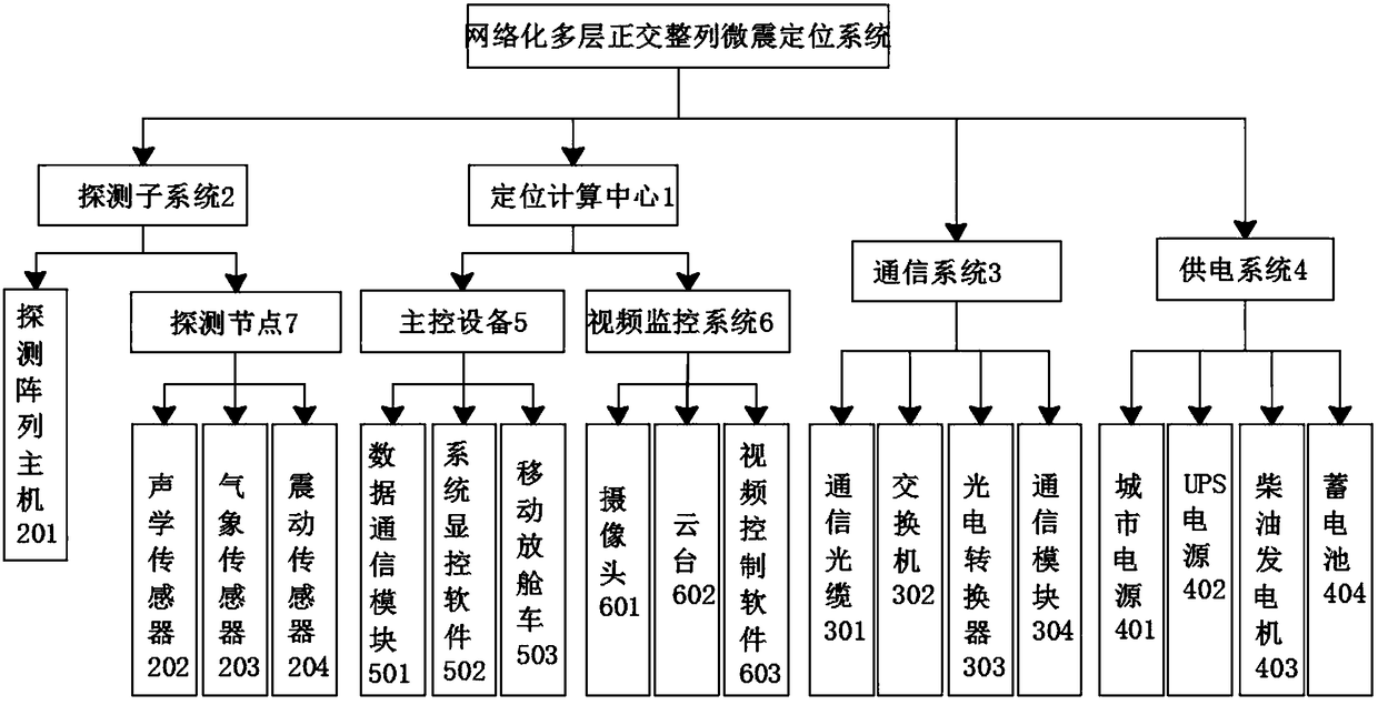
[0028] Such as figure 1 As shown, the present invention provides a networked multi-layer orthogonal array microseismic positioning system, including a positioning computing center 1, a detection subsystem 2, a communication system 3 and a power supply system 4, and the positioning computing center 1 includes a main control device 5 and a video monitoring System 6; detection subsystem 2 includes a detection array host 201 and a detection node 7 for networked node positions, the detection node 7 detects micro-vibration signals, the micro-seismic signals are preprocessed by the detection array host 201, and are sent back to the positioning calculation through the communication system 3 The center 1 performs positioning and calculation of the projectile landing point, and the microseismic detection array of the detection node 7 can perform synchronous timing through GPS or Beidou system; the communication system 3 is used for data interactive communication; the power supply system ...


PUM


Abstract

The invention discloses a micro-seismic positioning system for a networked multilayer orthogonal array, relating to the technical field of measurement of falling points. According to the micro-seismicpositioning system, the technical problems of high construction cost and damaging rate of existing equipment are solved. The micro-seismic positioning system comprises a positioning calculating center, a detection subsystem, a communication system and a power supply system, wherein the positioning calculating center comprises master control equipment and a visual monitoring system; and the detection subsystem comprises a detection array host and a networked node position detection node, the detection node is used for detecting a micro-seismic signal, and the micro-seismic is pretreated by virtue of the detection array host and is returned to the positioning calculating center through the communication system and is subjected to projectile falling point positioning calculation. Compared with single densely distributed sensor adopted in the prior art, the micro-seismic positioning system has the advantages that sensors are distributed in a multilayer orthogonal array manner to form a detection node, so that the construction cost of a target reporting system is substantially lowered, and meanwhile, the probability that detection system equipment is smashed by projectiles is reduced.

Description

technical field [0001] The invention relates to the technical field of drop point measurement, and in particular to a networked multi-layer orthogonal array microseismic positioning system. Background technique [0002] In the multi-type ground attack live ammunition shooting training, when determining the shooting accuracy, impact spread, and impact circle difference of various weapons, it is necessary to accurately locate the position of the impact point. The traditional manual target reporting method is to use manual on-site observation or optical measurement methods such as telescopes to judge the position of the projectile after the projectile lands and explodes. The timeliness is poor, the manpower consumption is large, the accuracy is poor, and the efficiency is low, which can no longer meet the needs of training in the information age. The actual needs of target shooting; at present, the target reporting method has developed into an automatic target reporting method ...

Claims


Application Information

Patent Timeline
Patent Type & Authority Applications(China)
IPC IPC(8): G01S5/22G01V1/28H04N7/18G08C19/00
CPCH04N7/18G08C19/00G01S5/22G01V1/288G01V2210/123
Inventor 黄黎明杨霄锋侯嘉伟
Owner 成都中欣科创声学科技有限公司
Learn More