Primary feeding and crushing shaft for straw crushing machine
A technology of straw grinder and crushing shaft, which is applied in the direction of application, agricultural machinery and tools, cutting equipment, etc., can solve the problems of slow feeding and cutting speed, and affect the effect of straw crushing, so as to improve cutting speed, cut materials easily, The effect of increasing the feed rate
- Summary
- Abstract
- Description
- Claims
- Application Information
AI Technical Summary
Problems solved by technology
Method used
Image
Examples
specific Embodiment approach 1
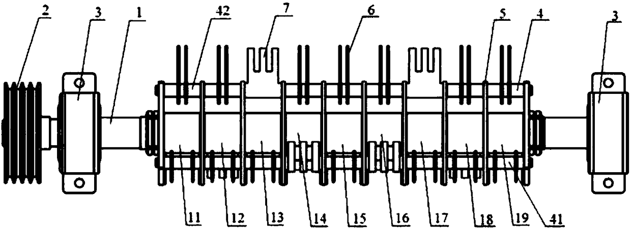
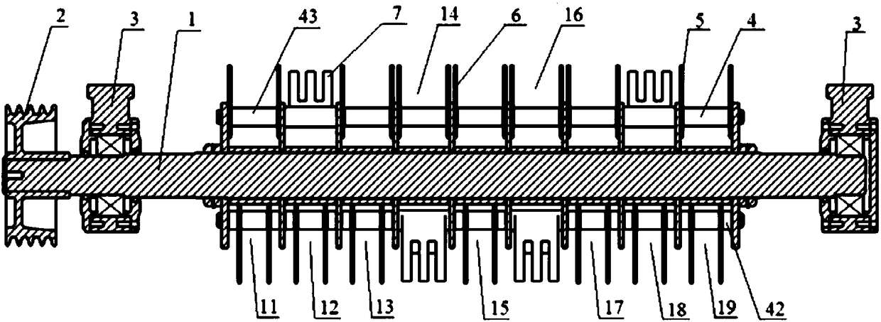
[0017] Specific implementation mode one: combine Figure 1 ~ Figure 3 Describe this embodiment, this embodiment includes a main shaft 1, an input pulley 2, two bearing blocks 3, three cutter shafts 4, six claws 7, several discs 5 and several cutters 6, the main shaft The two ends of 1 are supported in the bearing housing 3, the input pulley 2 is fixed on the input end of the main shaft 1, several discs 5 are located between the two bearing housings 3 and are fixed on the main shaft 1, and the three cutterhead shafts 4 are evenly distributed along the same circumference of the disk 5, and each cutter head shaft 4 passes through several disks 5 and is fixed on the disk 5,
[0018] The primary feed crushing shaft also includes, the intervals between several disks 3 are first interval 11, second interval 12, third interval 13, fourth interval 14, and fifth interval 15 from left to right. , the sixth interval 16, the seventh interval 17, the eighth interval 18 and the ninth interv...
specific Embodiment approach 2
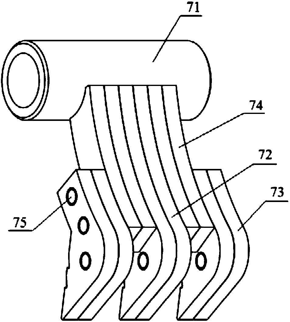
[0022] Specific implementation mode two: combination image 3 Describe this embodiment. In this embodiment, each claw 7 is composed of a shaft sleeve 71, a middle claw 72, two side claws 73 and two sets of partitions 74, and the two sets of partitions 74 are symmetrically arranged on the middle claw 72. The two side claws 73 are symmetrically fixed on both sides of the two side claws 73, and the middle claw 72, the two side claws 73 and the two sets of partitions 74 are connected by connecting elements. The upper ends of the plates 74 are fixedly connected with the shaft sleeve 71 , and the shaft sleeve 71 is sleeved on the cutter head shaft 4 . Other components and connections are the same as those in the first embodiment.
specific Embodiment approach 3
[0023] Specific implementation mode three: combination image 3 This embodiment is described. In this embodiment, three connecting element mounting holes 75 are provided on the middle claw 72 and the two side claws 73 , and the three connecting element mounting holes 75 are arranged from top to bottom. This is arranged in order to adjust the length of the finger 73 to adapt to the cutters 5 of different lengths. Other components and connections are the same as those in the second embodiment.
PUM
 Abstract
Description
Claims
Application Information
 - R&D
- Intellectual Property
- Life Sciences
- Materials
- Tech Scout
- Unparalleled Data Quality
- Higher Quality Content
- 60% Fewer Hallucinations
Browse by: Latest US Patents, China's latest patents, Technical Efficacy Thesaurus, Application Domain, Technology Topic, Popular Technical Reports.
© 2025 PatSnap. All rights reserved.Legal|Privacy policy|Modern Slavery Act Transparency Statement|Sitemap|About US| Contact US: help@patsnap.com


