
Automatic robot finger

A technology of robot finger and linear drive mechanism, which is applied in the direction of manipulators, collets, manufacturing tools, etc., can solve the problem that the caliper cannot realize single action, and achieve the effect of guaranteed clamping force, simple structure, and high driving pressure

Inactive Publication Date: 2018-06-08
张超
View PDF0 Cites 0 Cited by
  • Summary
  • Abstract
  • Description
  • Claims
  • Application Information

AI Technical Summary

Problems solved by technology

[0003] The technical problem to be solved by the present invention is: to overcome the technical problem that the calipers in the prior art cannot realize single action, and to provide an automatic robot finger

Method used


Image

  • Automatic robot finger
  • Automatic robot finger
  • Automatic robot finger

Examples


Embodiment Construction

[0021] The present invention is described in further detail now in conjunction with accompanying drawing. These drawings are all simplified schematic diagrams, which only illustrate the basic structure of the present invention in a schematic manner, so they only show the configurations related to the present invention.

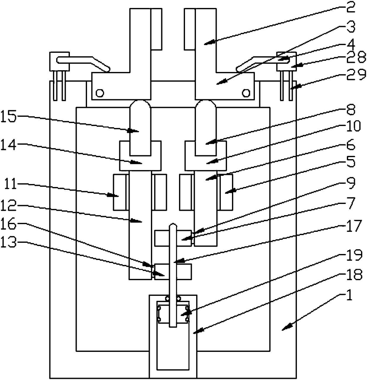
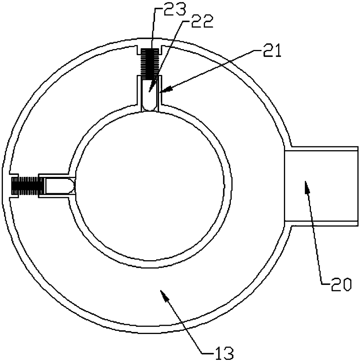
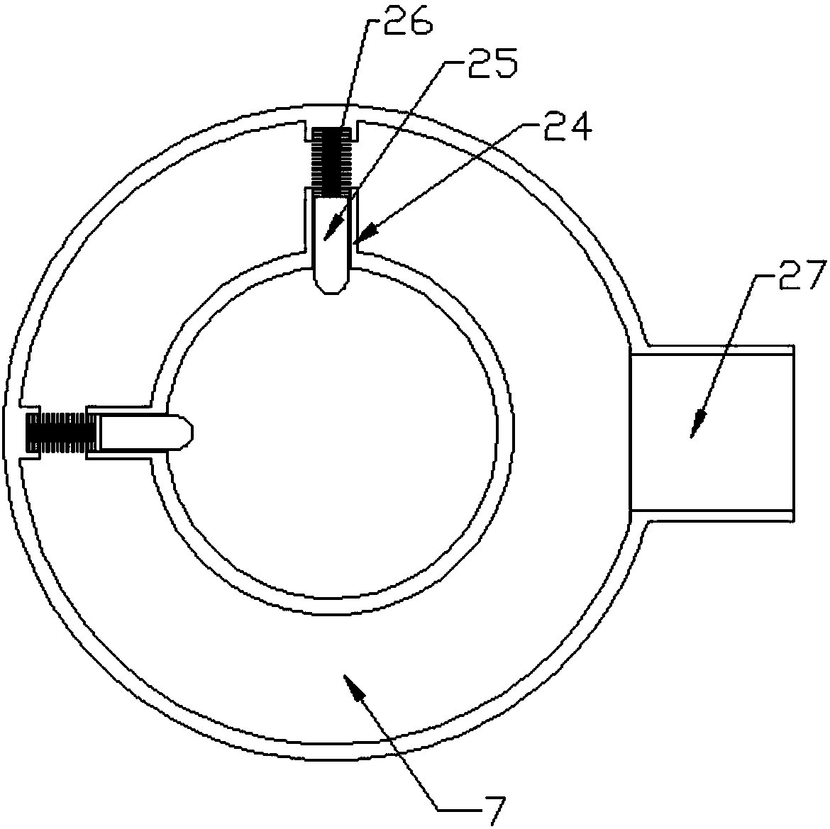
[0022] Such as Figure 1~3 As shown, the present invention is an automatic robot finger, including a caliper seat, a connection opening is arranged on the top of the caliper seat, and two groups of calipers are symmetrically arranged on the connection opening, and the position of the connection opening is elastically connected to the caliper. connected, the caliper includes a nipper and a top plate, the top plate and the nipper are connected in an L shape, wherein one end of the top plate is rotationally connected to the connection opening, and the other axial end of the top plate is provided with A pushing part, the nipper is connected to the back of the pus...


PUM


Abstract

The invention relates to an automatic robot finger. The automatic robot finger comprises a caliper seat; a connecting opening is formed in the top of the caliper seat; two sets of calipers are symmetrically disposed in the connecting opening; a driver is disposed at the bottoms of the calipers and comprises a linear driver body and two sets of ejector rods; the ejector rods are connected with a piston rod of the linear driver body through sliding rings; bolt blocks are disposed in the sliding rings and are positioned through the air pressure and springs; the number of the ejector rods drivingthe calipers to swing is controlled through combination and separation between the bolt blocks and the piston rod, and asynchronous pneumatic action of the calipers is achieved. A left driving sleeveand a right driving sleeve are driven through the air pressure, and separation and combination between the driving sleeves and a caliper linkage mechanism are achieved through the different pressures,so that a single-action mode or a double-action mode is achieved, the structure is simple, and the manufacturing cost is low.

Description

technical field [0001] The invention relates to an automatic robot finger, which belongs to the field of automatic equipment. Background technique [0002] Pneumatic fingers, also known as pneumatic grippers or pneumatic grippers, are actuators that use compressed air as power to grip or grab workpieces. It is mainly two sets of calipers with a linkage structure. There is a linkage mechanism between the two sets of calipers. A push cylinder is used to push the linkage mechanism to realize the release of the calipers, and then the other two calipers are clamped by the spring mechanism. Because of its structural limitations, The two sets of calipers can only be opened and closed synchronously, and single-sided calipers cannot be driven. Contents of the invention [0003] The technical problem to be solved by the present invention is to overcome the technical problem that the caliper cannot realize single action in the prior art, and provide an automatic robot finger. [00...

Claims


Application Information

Patent Timeline
Patent Type & Authority Applications(China)
IPC IPC(8): B25J15/00
CPCB25J15/00
Inventor 张超
Owner 张超
Learn More