Automobile engine heat dissipation device

A technology of automobile engine and heat dissipation device, applied in the direction of engine components, machine/engine, engine cooling, etc., can solve the problems of poor applicability, low heat dissipation efficiency, high noise, etc., achieve simple and scientific structure, convenient installation and disassembly, and reduce the occupation effect of space

Inactive Publication Date: 2018-06-08
WUHU RUNLAN BIOTECH CO LTD
View PDF5 Cites 1 Cited by
  • Summary
  • Abstract
  • Description
  • Claims
  • Application Information

AI Technical Summary

Problems solved by technology

[0002] An engine is a machine that can convert other forms of energy into mechanical energy, including internal combustion engines (gasoline engines, etc.), external combustion engines (Stirling engines, steam engines, etc.), electric motors, etc. The engine will overheat after driving for a long time At present, the engine is usually cooled with coolant to reduce heat damage to the engine, but the engine coolant will slowly evaporate and become less during use, which will eventually lead to a decrease in engine cooling capacity, resulting in engine failure and seriously affecting driving safety. Therefore, Growing demand for automotive engine cooling
[0003] The current car engine heats up seriously during driving, and the built-in heat dissipation system is unaffordable. At present, the external heat dissipation system of the engine on the market has a multi-position air cooling system, and the heat is discharged through the fan. Compared with water cooling, this method has low heat dissipation efficiency and noise. large, poor stability, and poor applicability of external cooling devices currently on the market, and engines of different sizes cannot be used universally. Therefore, a car engine cooling device is proposed to solve the above problems

Method used


Image

  • Automobile engine heat dissipation device
  • Automobile engine heat dissipation device
  • Automobile engine heat dissipation device

Examples


Embodiment Construction

[0022] The following will clearly and completely describe the technical solutions in the embodiments of the present invention with reference to the accompanying drawings in the embodiments of the present invention. Obviously, the described embodiments are only some, not all, embodiments of the present invention. Based on the embodiments of the present invention, all other embodiments obtained by persons of ordinary skill in the art without making creative efforts belong to the protection scope of the present invention.

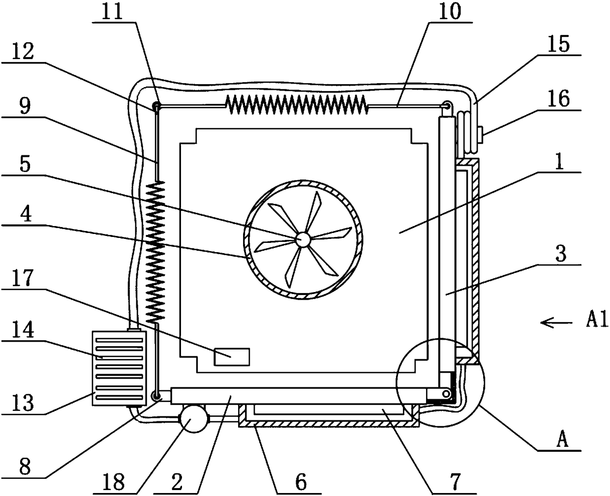
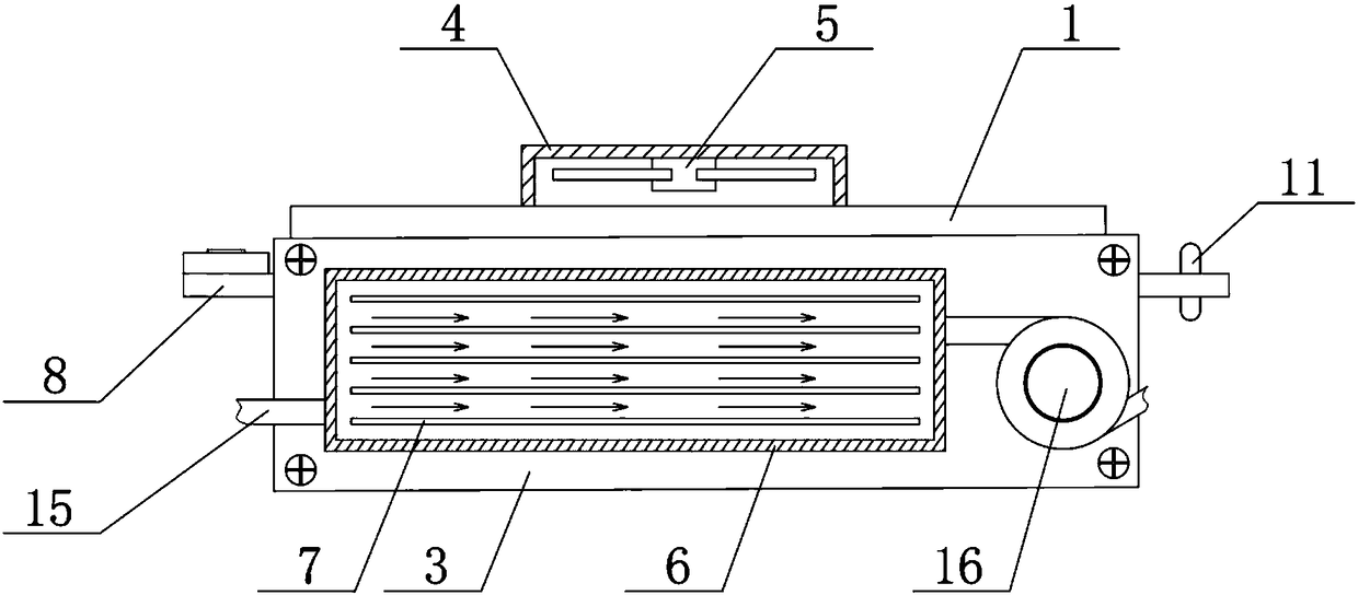
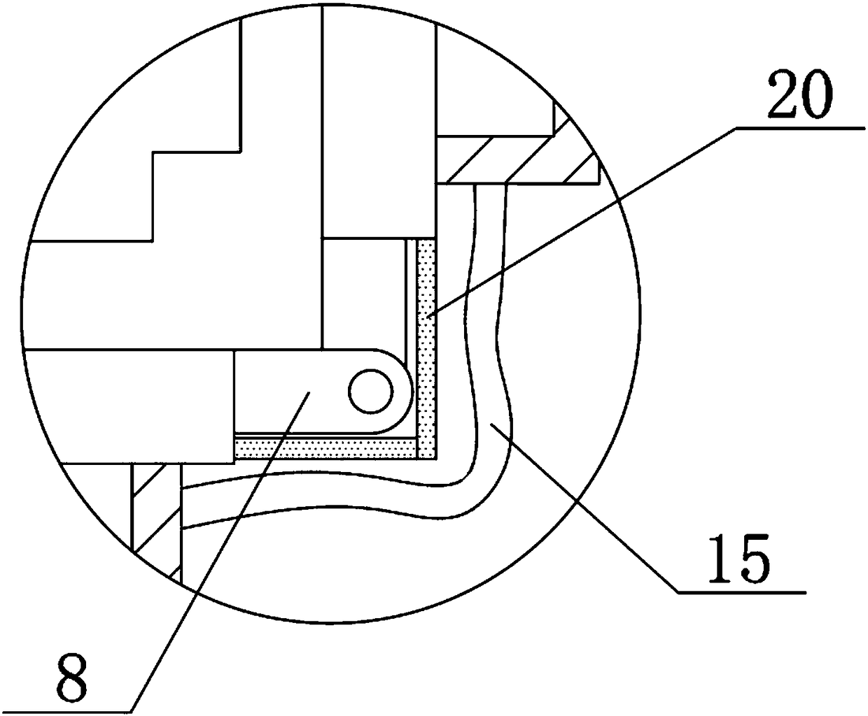
[0023] see Figure 1-4 , the present invention provides a technical solution:

[0024] An automobile engine cooling device, comprising a bottom heat-absorbing copper plate 2, a side heat-absorbing copper plate 3, a first telescopic spring 9 and a second telescopic spring 10, the bottom heat-absorbing copper plate 2 and the side heat-absorbing copper plate 3 are far away from the engine 1 One side of the box body 6 is fixedly connected with a plurality of heat...


PUM


Abstract

The invention relates to the technical field of automobiles, in particular to an automobile engine heat dissipation device. The device comprises a bottom heat absorbing copper plate, a side heat absorbing copper plate, a first telescopic spring and a second telescopic spring, the sides, away from the engine, of the bottom heat absorbing copper plate and the side heat absorbing copper plate are fixedly connected with box bodies, a plurality of heat conducting sheets are horizontally arranged on the box bodies, water cooling hoses are fixedly connected with two sides of the box bodies, the firsttelescopic spring, the second telescopic spring, the side heat absorbing copper plate and the bottom heat absorbing copper plate are connected end-to-end to form a square opening, an engine is arranged in the opening, a heat dissipation fan is arranged above the engine, a temperature control switch is arranged on the lower left portion at the top of the engine, and the water cooling hoses are sequentially communicated with a bottom box body of the bottom heat absorbing copper plate, a delivery pump, a heat dissipation box and a right box body of the side heat absorbing copper plate in the clockwise direction. According to the device, an external water cooling heat dissipation system is adopted, air cooling heat dissipation is adopted as an auxiliary manner to conduct heat dissipation on the engine, the cooling effect is good, the adaptability is wide, and the device is worthy of popularization.

Description

technical field [0001] The invention relates to the technical field of automobiles, in particular to a radiator for an automobile engine. Background technique [0002] An engine is a machine that can convert other forms of energy into mechanical energy, including internal combustion engines (gasoline engines, etc.), external combustion engines (Stirling engines, steam engines, etc.), electric motors, etc. The engine will overheat after driving for a long time At present, the engine is usually cooled with coolant to reduce heat damage to the engine, but the engine coolant will slowly evaporate and become less during use, which will eventually lead to a decrease in engine cooling capacity, resulting in engine failure and seriously affecting driving safety. Therefore, There is a growing need for automotive engine cooling units. [0003] The current car engine heats up seriously during driving, and the built-in heat dissipation system is unaffordable. At present, the external h...

Claims


Application Information

Patent Timeline
Patent Type & Authority Applications(China)
IPC IPC(8): F01P3/20F01P5/02F01P11/04F01P11/00
Inventor 不公告发明人
Owner WUHU RUNLAN BIOTECH CO LTD
Why Eureka
Try Eureka