
fluid pump

A fluid pump and housing technology, applied in the direction of pumps, parts of pumping devices for elastic fluids, pump elements, etc., can solve the problems of increasing the number of parts, tearing off retainers, increasing manufacturing costs, etc., to allow The effect of increasing errors, reducing the number of components, and reducing manufacturing costs

Active Publication Date: 2019-08-30
SHANGHAI HYACT TECH LTD
View PDF9 Cites 0 Cited by
  • Summary
  • Abstract
  • Description
  • Claims
  • Application Information

AI Technical Summary

Problems solved by technology

Therefore, during the use of the pump, wear of the retainer tends to occur, and there is a problem of poor durability.
[0005] In particular, during the process of pulling the piston out of the cylinder, a large load is applied to the connection between the retainer and the plunger shoe, and there is a problem that the retainer is torn off during this process
[0006] In addition, since the connection structure between the piston and the swash plate is composed of multiple parts, there is a problem that the number of parts increases and the assembly performance deteriorates.
Considering the connection between the piston and the swash plate, the assembly between the retainer and the plunger shoe, and the assembly between the piston and the plunger shoe are required, and the assembly requires precise operations, which makes automation difficult and further increases manufacturing cost

Method used


Image

  • fluid pump
  • fluid pump
  • fluid pump

Examples


Embodiment Construction

[0063] Hereinafter, some embodiments of the present invention will be described in detail with reference to illustrative drawings. It should be noted that when assigning reference numerals to constituent elements in the respective drawings, the same constituent elements are given the same reference numerals as much as possible even if they are shown in different drawings. In addition, in the description of the embodiments of the present invention, if it is considered that the detailed description of related known structures or functions hinders the understanding of the embodiments of the present invention, the detailed description is omitted.

[0064] In describing constituent elements of the embodiments of the present invention, terms such as first, second, A, B, (a) and (b) may be used. These terms are intended to distinguish a constituent element from other constituent elements, and these terms do not limit the nature, sequence or sequence of the constituent elements. When...


PUM


Abstract

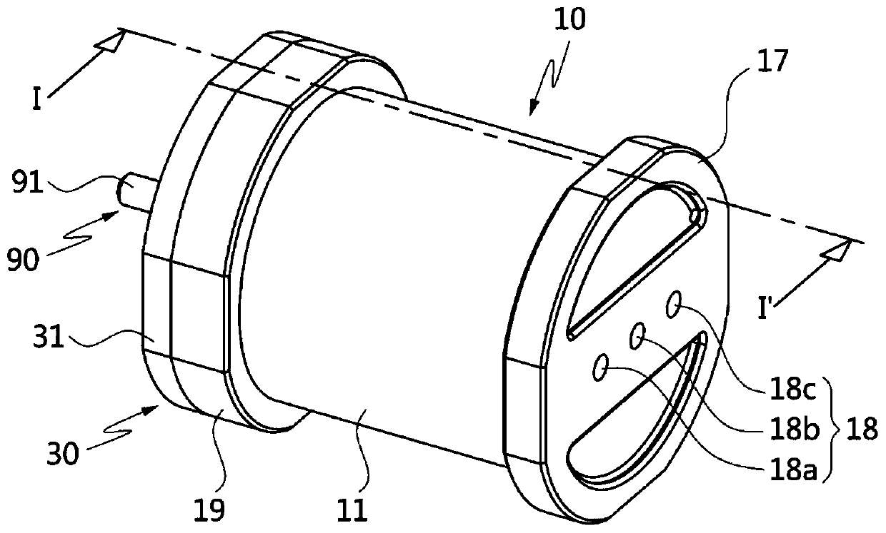
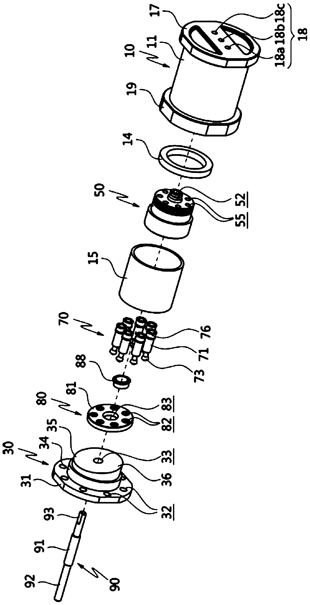
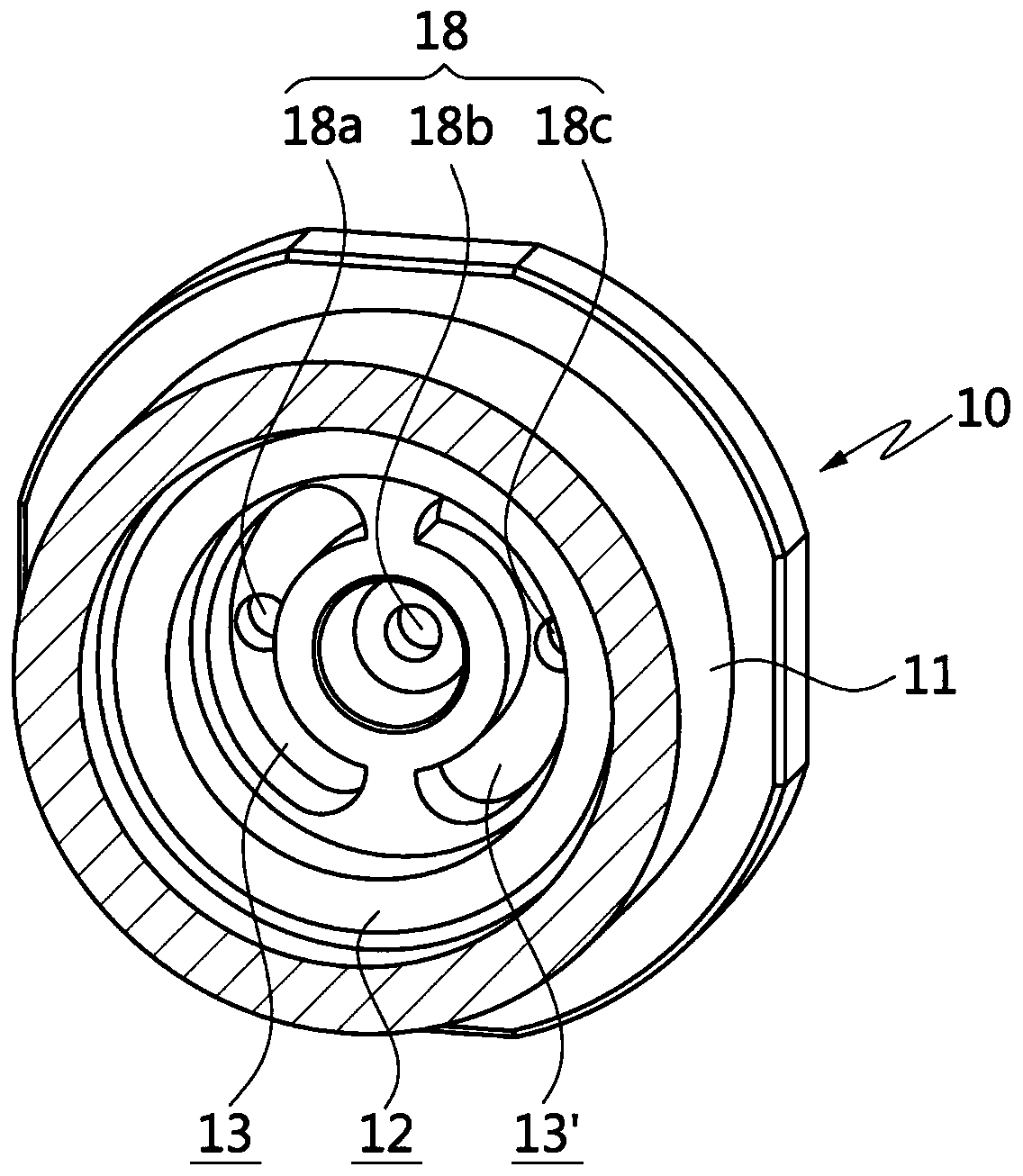
Provided is a fluid pump, comprising: a housing (10, 30) in which a driving space (12) is formed; a swash plate (35) located in the driving space (12) of the housing (10, 30), the swash plate being kept in a stationary state and having an inclined surface (36); a cylinder block (50) located inside the driving space (12) and rotating through a drive shaft (90), a plurality of cylinder holes (55) extending in the same direction as the drive shaft (90) inside the cylinder block (50); a plurality of piston assemblies (70), at least a portion of the piston assembly (70) being inserted inside the cylinder holes (55) of the cylinder block (50), performing a linear movement inside the cylinder holes (55) as the cylinder block (50) rotates, and one end of the piston assembly having a ball joint (73); and a disc shaped holder (80) combined with the swash plate (35) and maintaining in close contact with the inclined surface (36), wherein, the disc shaped holder (80) can rotate independently from the swash plate (35), the disc shaped holder (80) is connected with the ball joint (73) of the piston assembly (70), and the disc shaped holder (80) rotates together with the piston assembly (70) in the condition that the piston assembly (70) closely contacts with the inclined surface (36) of the swash plate (35). During the movement of the fluid pump, the wear of the holder (80) is reduced and the noise is reduced.

Description

technical field [0001] The present invention relates to a fluid pump (fluid pump), in particular to a disc-shaped retainer arranged on a swash plate that rotates independently of the swash plate, so that a piston connected to the retainer generates fluid pressure (oil pressure or Hydraulic fluid pump. Background technique [0002] A general fluid pump, such as a hydraulic pump, utilizes a phenomenon in which a phase changes when a swash plate (Swash Plate) inclined to one side rotates. A simple observation of its structure shows that the piston, which generates fluid pressure through linear movement inside the cylinder, is connected to the retainer through the plunger shoe. The retainer acts as a suspension for the plunger shoe, and since the retainer is adjacent to the swash plate, the result is that the piston can come into close contact with the swash plate. At this time, the retainer is connected with the cylinder through the piston, so that the retainer also rotates i...

Claims


Application Information

Patent Timeline
Patent Type & Authority Patents(China)
IPC IPC(8): F04B1/22F04B53/00
CPCF04B1/2014F04B1/22
Inventor 李涌权
Owner SHANGHAI HYACT TECH LTD
Learn More