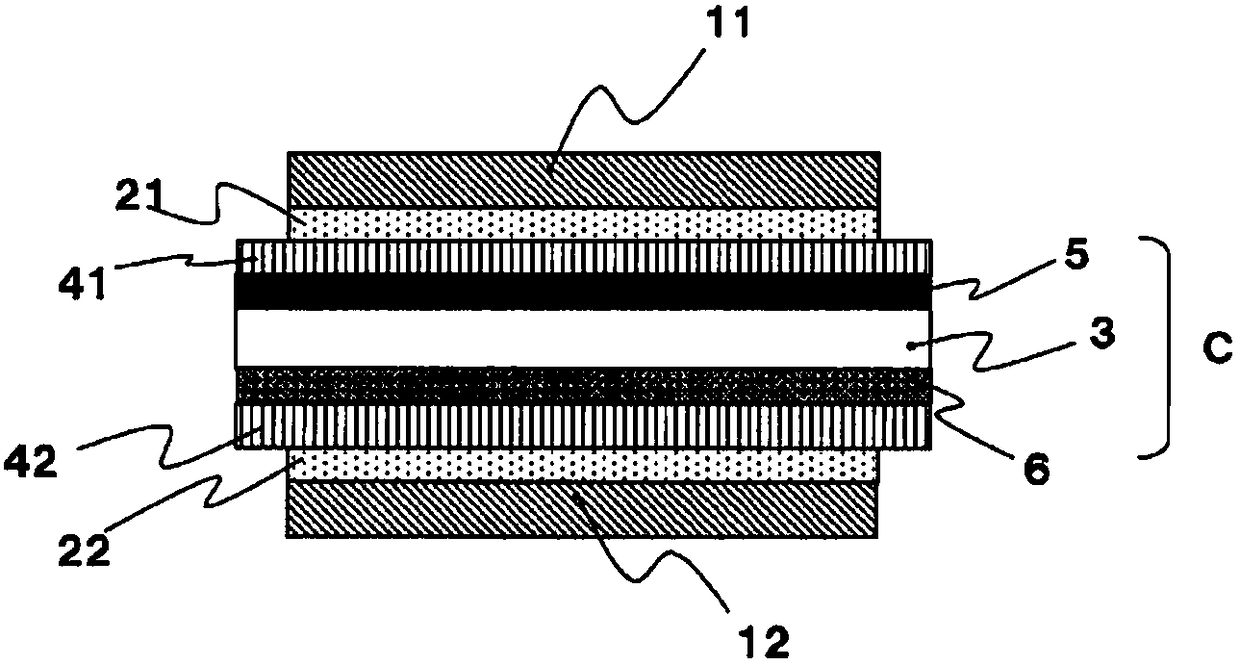
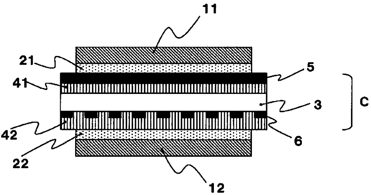
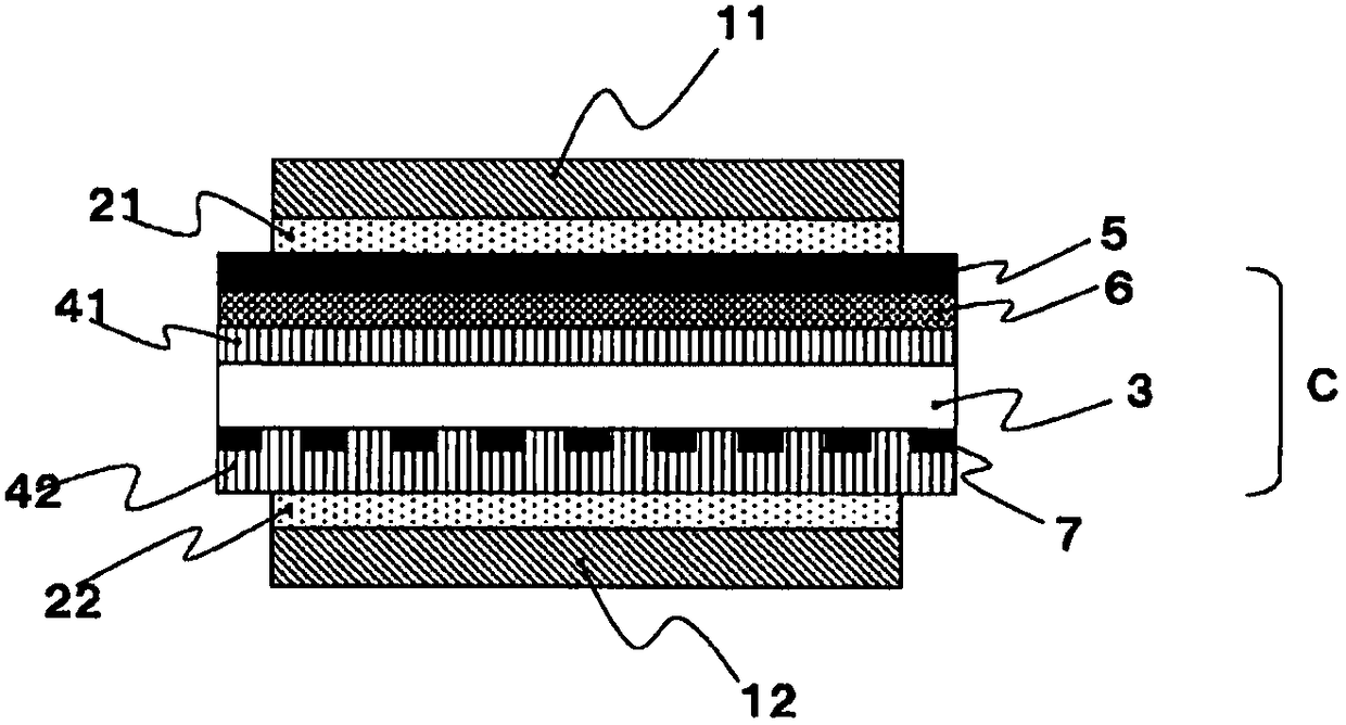
Liquid crystal panel with touch sensing function and liquid crystal display device

A technology of touch sensing and liquid crystal panel, which is applied in the direction of identification device, data processing input/output process, instrument, etc. It can solve the problems of unstable sensor electrode capacity, electric field disorder, and touch panel sensitivity reduction, etc., and achieve uneven suppression , Compatibility improvement, and the effect of suppressing static electricity

Active Publication Date: 2018-06-08
NITTO DENKO CORP
View PDF19 Cites 6 Cited by
  • Summary
  • Abstract
  • Description
  • Claims
  • Application Information

AI Technical Summary

Problems solved by technology

When there is a conductive layer such as an antistatic layer between the above-mentioned transparent electrode pattern and the user's finger, the electric field between the drive electrode and the sensor electrode is disturbed, the capacitance of the sensor electrode becomes unstable, the sensitivity of the touch panel decreases, and malfunction occurs. s reason

Method used


Image

  • Liquid crystal panel with touch sensing function and liquid crystal display device
  • Liquid crystal panel with touch sensing function and liquid crystal display device
  • Liquid crystal panel with touch sensing function and liquid crystal display device

Examples


Embodiment 1

[0149] (Preparation of Acrylic Polymer (A))

[0150] Add 75.8 parts of butyl acrylate, 23 parts of phenoxyethyl acrylate, 0.5 parts of N-vinyl-2-pyrrolidone (NVP), and A monomer mixture of 0.3 parts and 0.4 parts of 4-hydroxybutyl acrylate. Further, 0.1 part of 2,2'-azobisisobutyronitrile as a polymerization initiator was added together with 100 parts of ethyl acetate to 100 parts of the above-mentioned monomer mixture (solid content), and nitrogen gas was introduced while stirring slowly. After nitrogen replacement, the liquid temperature in the flask was kept at about 55° C., and polymerization was carried out for 8 hours to prepare a solution of acrylic polymer (A) with a weight average molecular weight (Mw) of 1.6 million and Mw / Mn=3.7.

[0151] (Preparation of Adhesive Composition)

[0152]With respect to 100 parts of solid content of the solution of the acrylic polymer (A1) obtained in Production Example 1, lithium bis(trifluoromethanesulfonyl)imide (Li- TFSI) 0.1 par...

Embodiment 2~14、 comparative example 1~6

[0156] In Example 1, as shown in Table 1, the amount of N-vinyl-2-pyrrolidone (NVP) used in the monomer mixture used in the preparation of the acrylic polymer (A) and the adhesive composition were changed. Except for the type of ionic compound (Li-TFSI or MPP-TFSI) or its compounding ratio, and the type of polarizing film used in the preparation, a solution of an acrylic polymer was prepared in the same manner as in Example 1. , A solution of an acrylic adhesive composition. Moreover, using the solution of this acrylic adhesive composition, it carried out similarly to Example 1, and produced the polarizing film with an adhesive layer.

[0157] The following evaluations were performed about the polarizing film with an adhesive layer obtained in the said Example and the comparative example. Table 1 shows the evaluation results. In addition, in each evaluation, "initial" is the value measured immediately after making the polarizing film with an adhesive layer, and "after humidi...


PUM

PropertyMeasurementUnit
thicknessaaaaaaaaaa
thicknessaaaaaaaaaa
thicknessaaaaaaaaaa

Abstract

The invention provides a liquid crystal panel with touch sensing function, which is capable of exhibiting satisfactorily stable antistatic function even in a humidified environment. A liquid crystal panel with touch sensing function, which comprises: a first polarizing film that is arranged on the viewing side of a liquid crystal cell with touch sensing function; a second polarizing film that is arranged on the side opposite to the viewing side; and a first adhesive layer that is arranged between the first polarizing film and the liquid crystal cell. The first adhesive layer is formed from anadhesive composition containing: a (meth)acrylic polymer (A) which contains, as monomer units, an alkyl (meth)acrylate (a1) and an amide group-containing monomer (a2); and an ionic compound (B). In addition, the first adhesive layer undergoes a small change in the surface resistivity even in a humidified environment.

Description

technical field [0001] The invention relates to a liquid crystal panel with a touch sensing function and a liquid crystal display device. The liquid crystal display device with a touch sensor function of the present invention can be used as various input display devices such as mobile devices. Background technique [0002] In a liquid crystal display device, a polarizing film is usually bonded from both sides of a liquid crystal cell via an adhesive layer depending on the image forming method. In addition, products in which a touch panel is mounted on a display screen of a liquid crystal display device are also put into practical use. There are various types of touch panels such as capacitive, resistive film, optical, ultrasonic, and electromagnetic induction, but capacitive types are beginning to be widely used. In recent years, a liquid crystal display device with a touch sensor function incorporating a capacitive sensor as a touch sensor portion has been used. [0003]...

Claims


Application Information

Patent Timeline
Patent Type & Authority Applications(China)
IPC IPC(8): G02F1/1335B32B27/30G02B5/30G02F1/1333G06F3/041G06F3/044G09F9/00
CPCG02F1/133528G02F1/13338G02B1/16B32B7/12B32B33/00B32B17/06C09J133/066G02F2202/22G02F2202/28G06F3/0412G02B1/00G06F3/044G02B5/30G09F9/00B32B27/30G02F1/1335G06F3/041B32B2457/202C09J2203/318C09J2400/16C09K2323/05C09K2323/057C09K2323/00C09K2323/031C09K2323/03C09K2323/04C09K2323/035G02F1/133562G02F1/133567B32B27/308B32B2457/208
Inventor 山本悟士木村智之外山雄祐
Owner NITTO DENKO CORP
Why Eureka
Try Eureka