Height-adjustable fusion cage

A cage and adjustable technology, applied in medical science, prosthesis, spinal implants, etc., can solve the problems of difficult to insert matching type cage, difficult to continuously adjust the size, etc., achieve small size, achieve continuous adjustment, Promotes minimally invasive effects

Pending Publication Date: 2018-06-12
SHANGHAI REACH MEDICAL INSTR
View PDF0 Cites 1 Cited by
  • Summary
  • Abstract
  • Description
  • Claims
  • Application Information

AI Technical Summary

Problems solved by technology

However, at present, most of the fusers are conventional specifications with fixed model size, it is difficult to realize continuous size adjustment, and it is difficult to place a matching model fuser under the endoscope channel

Method used


Image

  • Height-adjustable fusion cage
  • Height-adjustable fusion cage
  • Height-adjustable fusion cage

Examples


Embodiment example 1

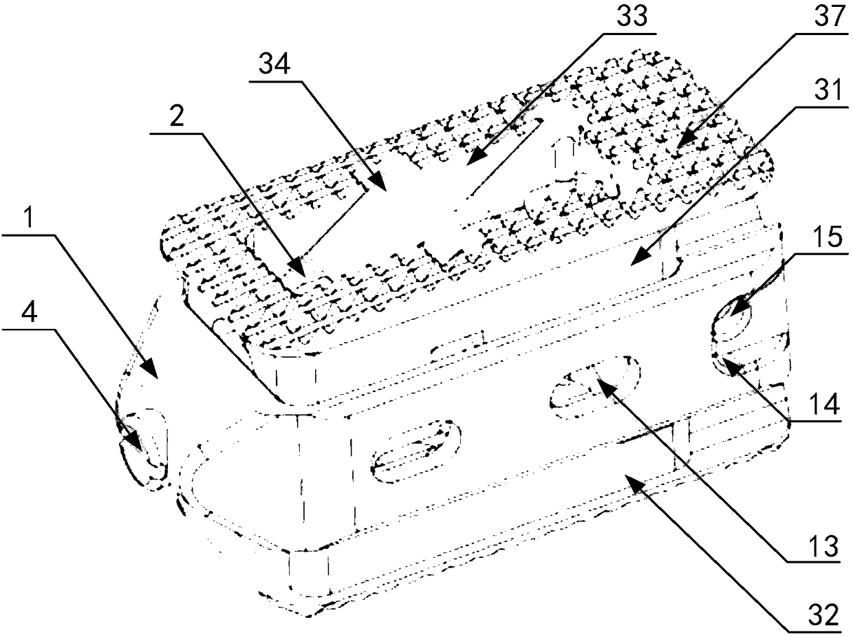
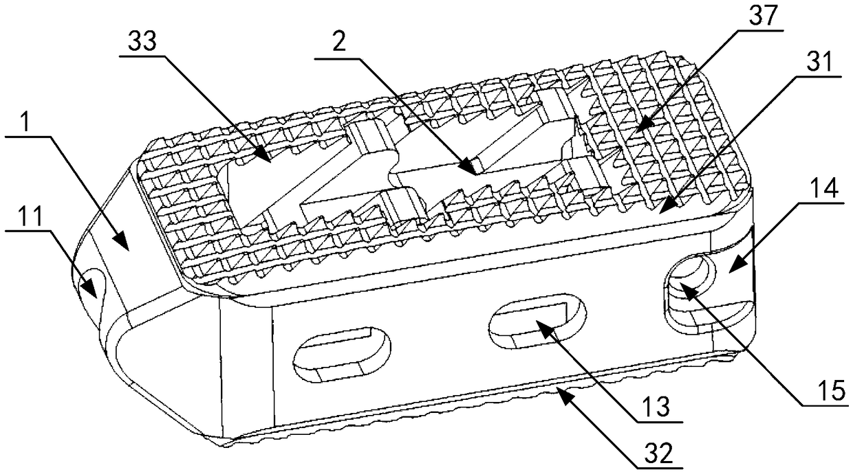
[0032] like Figure 1 to Figure 2 As shown, the present invention proposes a height-adjustable cage, including a cage base 1 , a transmission block 2 , a clasp (not shown in the figure), an upper cover 31 and a lower cover 32 .

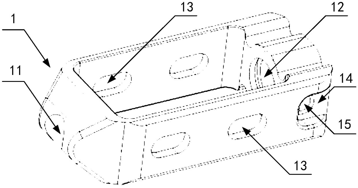
[0033] Specifically, such as image 3 As shown, the fusion device base 1 includes a left wall, a right wall, a front end and a rear end, the center of the front end is provided with a first through hole 11, and the center of the rear end is provided with a second through hole 12, so The second through hole 12 is provided with a ring groove structure (not shown) that matches the snap ring; further, in this embodiment, the preferred solution is: both the left wall and the right wall are provided with a second Four through holes 13 allow the bone cement to flow out and contact the bone, and the rear end of the cage base 1 is provided with a second groove structure 14 matching with the surgical tool, and the inner wall of the second groove structure 14 i...

Embodiment example 2

[0039] like Figure 9 to Figure 10 As shown, this implementation case is a further improvement on the basis of implementation case one. The technical solution described in embodiment one is also applicable to this implementation case. The difference from implementation case one is that the upper cover plate 31 and The structure and manufacturing method of the lower cover plate 32 are different. The upper cover plate 31 and the lower cover plate 32 are both integrally formed by three-dimensional printing, and the upper cover plate 31 and the lower cover plate 32 are provided with vertically penetrating plants. A bone hole 33, the bone graft hole 33 is provided with a grid structure 38, the design of the grid structure 38 is conducive to the growth of the bone, avoiding the step of bone grafting.

[0040] Further, in this embodiment, the preferred solution is: the upper cover plate 31 and the lower cover plate 32 are processed by three-dimensional printing, which facilitates the...


PUM


Abstract

The invention provides a height-adjustable fusion cage, which comprises a fusion cage base, a transmission block, a retaining ring, an upper cover plate and a lower cover plate, wherein the transmission block is arranged in the fusion cage base, and the specific position of the transmission block is adjusted via a screw, so that the transmission block can do axial movement in the fusion cage base;along with the movement of the transmission block, the upper cover plate and the lower cover plate, which are connected to the transmission block in a clamped and embedded mode, do synchronous movement along the direction of convex ribs of the transmission block convex ribs, so that a distance between the upper cover plate and the lower cover plate is changed, and the height of the fusion cage isadjusted. According to the height-adjustable fusion cage provided by the invention, the position of the transmission block is adjusted via the screw, and the height of the fusion cage is adjusted through a linkage action between the transmission block and the upper and lower cover plates, which move in the front-back direction, so that continuous adjustment of the fusion cage in accordance with models and sizes is achieved and various individual demands are satisfied. Meanwhile, the height-adjustable fusion cage has the advantages of being small in size, convenient to implant, applicable to minimally invasive spinal fusion under an endoscope, beneficial for promoting minimal invasion of interbody fusion and the like.

Description

technical field [0001] The invention relates to the field of medical instruments, in particular to a fusion device with adjustable height. Background technique [0002] Spinal degenerative disease is a common disease, among which the treatment of lumbar degenerative spondylolisthesis, segmental instability, intervertebral discogenic disease, traumatic spondylolisthesis, etc. generally requires lumbar fixation and fusion. The application of the intervertebral fusion device can maintain the height of the intervertebral space, restore the support of the anterior and middle columns, increase the capacity of the intervertebral foramen, relieve the compression of the nerve roots, and prevent the collapse of the intervertebral space and the formation of pseudarthrosis. With the development of minimally invasive surgery, higher requirements are placed on the design of intervertebral fusion devices. On the other hand, with the application of endoscopic technology in surgery, minimal...

Claims


Application Information

Patent Timeline
Patent Type & Authority Applications(China)
IPC IPC(8): A61F2/44
CPCA61F2/4455A61F2/447A61F2002/30556A61F2002/30622
Inventor 黄孝敏谈俊杰赵东民
Owner SHANGHAI REACH MEDICAL INSTR
Why Eureka
Try Eureka