Construction Method of Underground Diaphragm Wall Using Assembled Lockpipe Waterstop Structure
A technique for underground diaphragm walls and construction methods, applied in underwater structures, infrastructure engineering, water conservancy projects, etc., can solve problems such as low rigidity and weak shear resistance of underground diaphragm walls, and achieve reduction of extubation force, Effect of increasing wall depth and decreasing contact area
- Summary
- Abstract
- Description
- Claims
- Application Information
AI Technical Summary
Problems solved by technology
Method used
Image
Examples
Embodiment 1
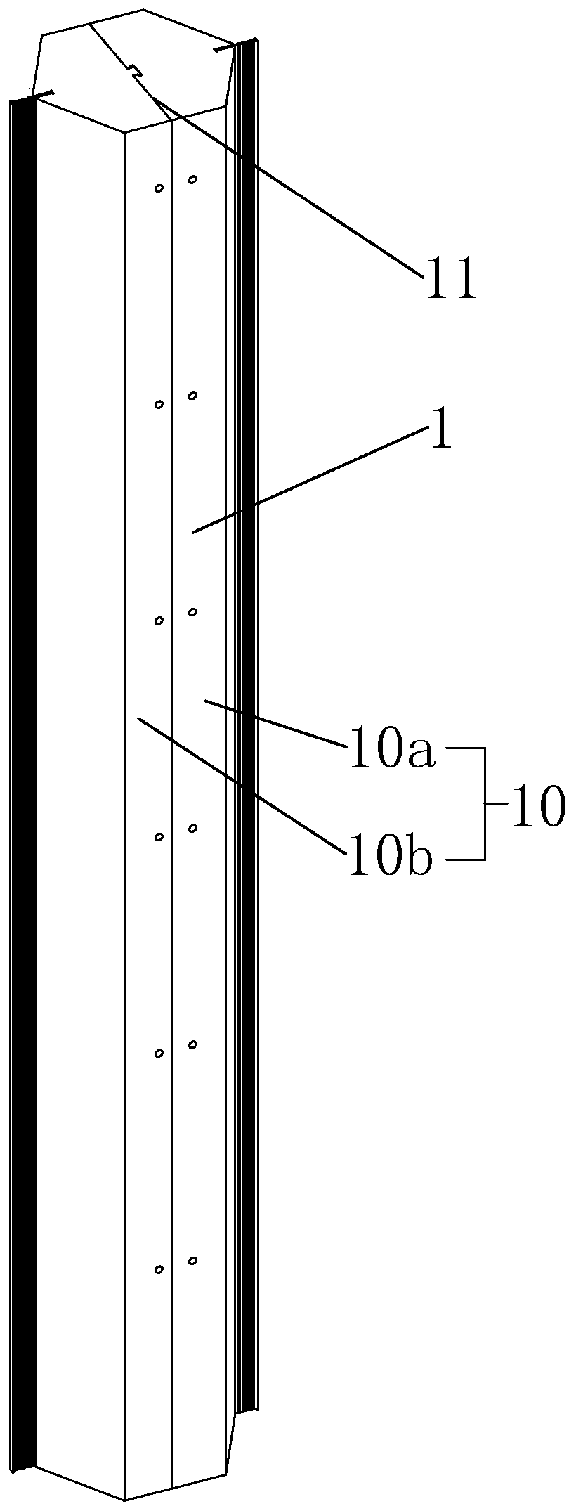
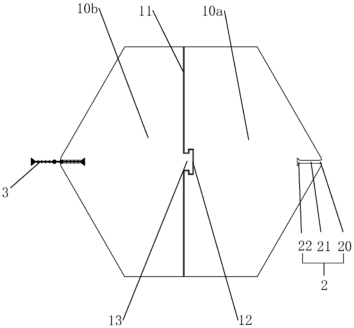
[0061] An assembled locking pipe, such as figure 1 As shown, including the pipe body 1, the cross section of the pipe body 1 is a regular hexagon. The pipe body 1 includes two semi-hexagonal steel pipes 10, the two semi-hexagonal steel pipes 10 are formed by dividing the centers of two sides corresponding to the pipe body 1 along the generatrix, and the two semi-hexagonal steel pipes 10 The semi-hexagonal steel pipe 10a and the semi-hexagonal steel pipe 10b are in sequence. Wherein the semi-hexagonal steel pipe 10a and the semi-hexagonal steel pipe 10b are assembled together to form the assembly surface 11 .
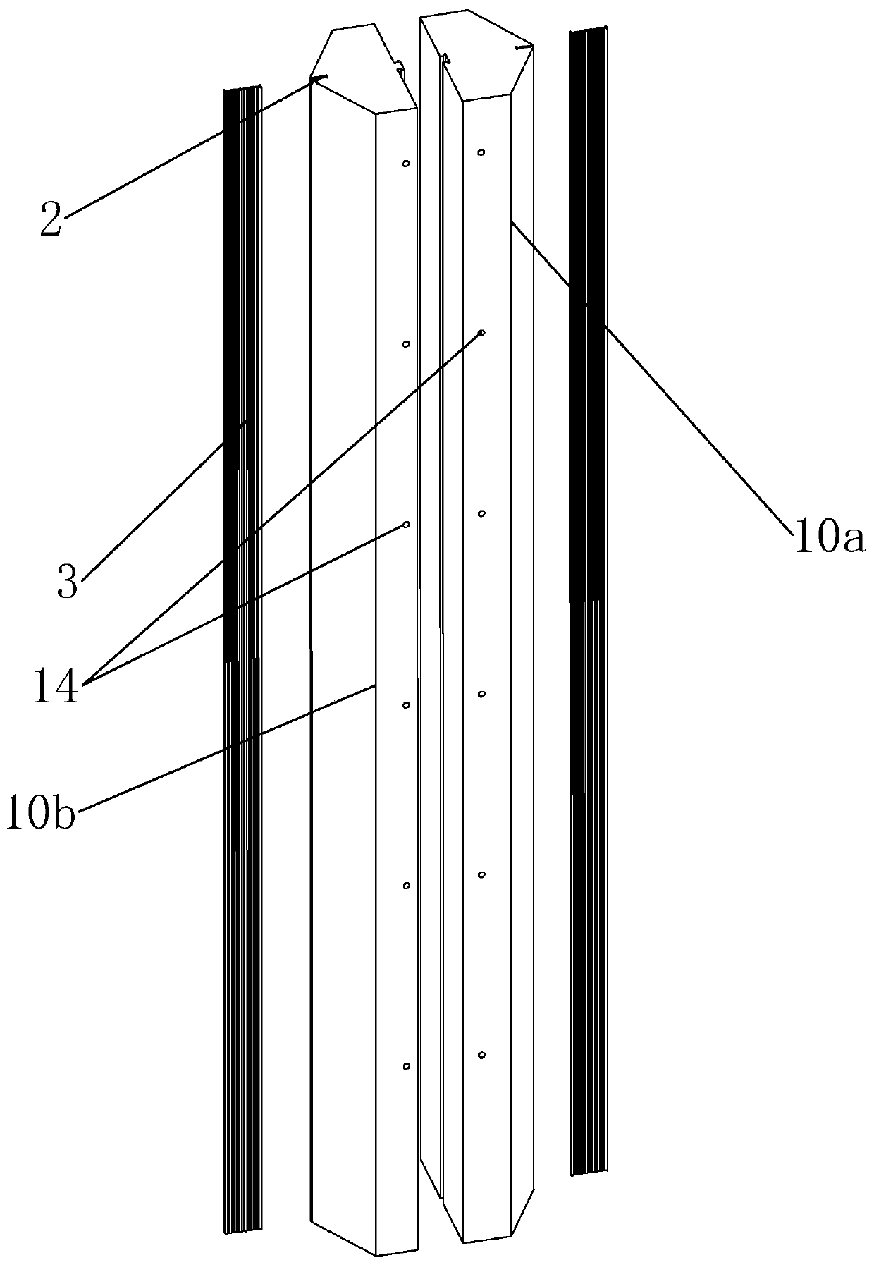
[0062] combine figure 2 and image 3 , The semi-hexagonal steel pipe 10a is provided with an assembly groove 12 at the center of the assembly surface 11, and the assembly groove 12 is concave inward along the radius of the semi-hexagonal steel pipe 10a. The assembling groove 12 is T-shaped, wherein the T-shaped head faces the inside of the half-hexagonal steel pipe ...
Embodiment 2
[0070] A construction method for an underground diaphragm wall using an assembled locking pipe water-stop structure, combining Figure 5 to Figure 8 , the construction method of the underground diaphragm wall is as follows:
[0071] A1: guide wall 5 construction: combined Figure 5 , use marking equipment to mark the construction range of the underground diaphragm wall 7, then use mechanical excavation of the base soil layer 4 to form a pit about 1.5 meters deep, and insert L-shaped steel bars 40 on both sides of the pit, and L-shaped steel bars 40 A baffle is set up on the outside, and concrete is poured to form a guide wall 5;
[0072] A2: Digging the first slot section 41: Combining Figure 6 and Figure 15 , after the guide wall 5 is solidified, use a hydraulic grab groover to dig deep into the base soil layer 4 below the guide wall 5 to form the first groove section 41;
[0073] A3: Construction of the first underground diaphragm wall 70:
[0074] (1) combination F...
Embodiment 3
[0098] A kind of manufacturing method of the assembled locking pipe described in the processing embodiment 1:
[0099] S1 Take a piece of steel plate 1D80, start from the starting point 800, and bend it twice in the same direction, the first time is 90 degrees, the second time is 120 degrees, refer to Figure 17 , the bent boards are respectively named as the first board 801, the second board 802 and the third board 803;
[0100] S2 Continue to bend at the first inflection point 804 away from the starting point 800 on the third plate body 803 to form the clamping groove 2 described in Embodiment 1, and the bending of the clamping groove 2 stops at the stop point 805;
[0101] S3 On the basis of S2, continue to bend the steel plate 1D800 twice along the original bending direction with the bending stop point 805 of the clamping groove 2 to form the fourth plate body 806 and the fifth plate body 807, and the third plate body The angle between 803 and the fourth plate 806 is 120 ...
PUM
 Abstract
Description
Claims
Application Information
 - R&D
- Intellectual Property
- Life Sciences
- Materials
- Tech Scout
- Unparalleled Data Quality
- Higher Quality Content
- 60% Fewer Hallucinations
Browse by: Latest US Patents, China's latest patents, Technical Efficacy Thesaurus, Application Domain, Technology Topic, Popular Technical Reports.
© 2025 PatSnap. All rights reserved.Legal|Privacy policy|Modern Slavery Act Transparency Statement|Sitemap|About US| Contact US: help@patsnap.com


