Tunnel supporting lagging jack and using method

A technology for arch frames and tunnels, which is applied in tunnels, tunnel linings, earthwork drilling and mining, etc. It can solve the problems that affect the quality and safety of engineering construction, the difficulty of controlling the tightness of prefabricated wedges, and the local concentration of loads, etc., so as to improve construction efficiency. The effect of low production cost and roughly consistent degree of tightness

Inactive Publication Date: 2018-06-12
SOUTHWEST PETROLEUM UNIV
View PDF9 Cites 10 Cited by
  • Summary
  • Abstract
  • Description
  • Claims
  • Application Information

AI Technical Summary

Problems solved by technology

[0005] The purpose of the present invention is to: in the prior art, when the steel arch is used to support the excavation surface of the surrounding rock, it is difficult to control the degree of tightness of the prefabricated wedges, and the steel arch is partially or completely suspended in the air, resulting in the local concentration of the steel arch. The effect of load or bias load can easily cause deformation and damage, and then affect the quality and safety of engineering construction. A tunnel support arch frame and its use method are provided. The tightness of the excavation surface is controlled, which solves the problem of local concentration of load when the steel arch supports the excavation surface of the surrounding rock, and ensures that the support device is supported along the ring of the tunnel section, ensuring construction quality and construction safety

Method used


Image

  • Tunnel supporting lagging jack and using method
  • Tunnel supporting lagging jack and using method
  • Tunnel supporting lagging jack and using method

Examples


Embodiment 1

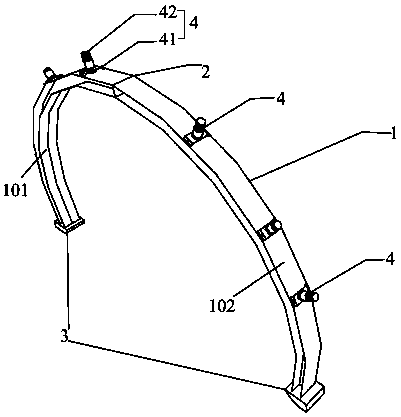
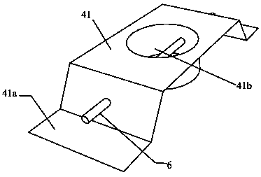
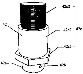
[0055] Tunnel support arches such as figure 1 , figure 2 , image 3 and Figure 4 As shown, it includes an annular arch main structure 1 arranged along the inner wall of the tunnel, and a plurality of support structures 4 connected to the arch main structure 1, and one end of the support structures 4 is connected to the arch main structure 1 , the other end is provided with a telescopic device 42 that expands and contracts to one side of the surrounding rock 5, so that the support structure 4 can be extended to the surrounding rock 5, and contacts with the surrounding rock 5 to form a support.

[0056] The arch main structure 1 is arranged on the inner wall of the tunnel and arranged circularly along the inner wall of the tunnel, so that after a plurality of support structures 4 are connected to the main arch structure 1, the excavation surface is supported from multiple positions, so that the tunnel support arch has multiple To avoid local excessive concentration of load ...

Embodiment 2

[0072] The use of tunnel support arches, such as Figure 1~4 As shown, when using the tunnel supporting arch as in Embodiment 1, follow the steps below:

[0073] a. Prefabricated and spliced ​​arch main structure 1;

[0074] b. Determine the support point;

[0075] c. Install the support structure 4;

[0076] d. Operate the telescopic device 42 so that the telescopic device 42 is against the excavation surface of the surrounding rock 5;

[0077] e. Step c and step d are repeated until all supporting structures 4 are installed.

[0078] During operation, the extension length of the telescopic device 42 is adjusted according to the distance between the arch main structure 1 and the surrounding rock 5, so that the support structure 4 presses the surrounding rock 5 tightly to ensure that each position of the arch main structure 1 The degree of tightness is roughly the same, so that the tunnel supporting arch is evenly stressed, ensuring the safe and reliable operation of the t...


PUM


Abstract

The invention relates to the technical field of tunnel engineering construction, in particular to a tunnel supporting lagging jack and a using method. The tunnel supporting lagging jack comprises an annular lagging jack main body structure arranged along the inner wall of a tunnel, and a plurality of supporting structures connected to the lagging jack main body structure. One ends of the supporting structures are connected to the lagging jack main body structure, and the other ends of the supporting structures are provided with telescopic devices stretching out and drawing back towards one side of surrounding rock so that the supporting structures can extend to reach the surrounding rock and in contact with the surrounding rock to form an effective support. According to the tunnel supporting device, by arranging the telescopic structures, control over the attaching tightness degree is conducted on an excavation face of the surrounding rock through the telescopic structures, the problemthat loads are concentrated when a steel lagging jack supports the excavation face of the surrounding rock is solved, it is ensured that the supporting device provides annular support along the crosssection of the tunnel, and the construction quality and construction safety are ensured.

Description

technical field [0001] The invention relates to the technical field of tunnel engineering construction, in particular to a tunnel support arch frame and a method for using it. Background technique [0002] Tunnel construction has always been an aspect that needs to be controlled in the process of road and railway construction. However, no matter whether the traditional mining method or the new Austrian method is used for construction, there is a problem: after blasting, the excavation surface is somewhat different from the expected effect, and the flatness of the excavation surface is poor. [0003] Due to the poor flatness of the excavation surface, there are great difficulties in the initial support. Specifically: it is difficult for the steel arch frame to be in close and comprehensive direct contact with the blasted surrounding rock, and even if it does, it is only partially in contact. In addition, since the erection position of the steel arch frame is selected by the ...

Claims


Application Information

Patent Timeline
Patent Type & Authority Applications(China)
IPC IPC(8): E21D11/18E21D11/22
CPCE21D11/18E21D11/183E21D11/186E21D11/22
Inventor 李雪张军伟黄新淼
Owner SOUTHWEST PETROLEUM UNIV
Why Eureka
Try Eureka