Multistage charging aging equipment

A technology of aging equipment and aging rack, which is applied in the direction of measuring electricity, measuring electrical variables, measuring devices, etc., can solve the problems of high cost and large power consumption, and achieve the effect of reducing aging cost, reducing energy consumption, and reducing energy loss

Pending Publication Date: 2018-06-12
山东鸿卓新能源科技股份有限公司
View PDF3 Cites 1 Cited by
  • Summary
  • Abstract
  • Description
  • Claims
  • Application Information

AI Technical Summary

Problems solved by technology

[0006] If each device is aged, it will consume a lot of power in the aging test
Now some methods have been proposed to recover energy from aging equipment, some are to convert it into alternating current and return it to the grid, some are to heat the solar energy, etc., but the cost is relatively high, so few companies use such equipment, so they provide a method that can recycle parts Electric energy, reduce electric energy consumption, low-cost charging aging equipment is very necessary

Method used


Image

  • Multistage charging aging equipment
  • Multistage charging aging equipment

Examples


Embodiment 1

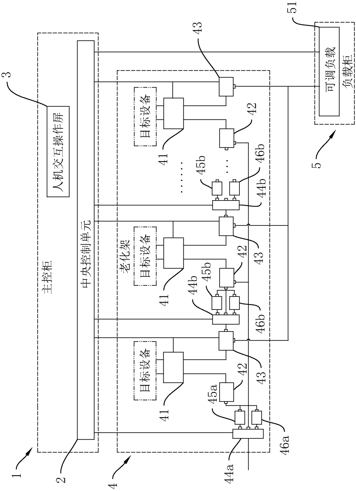
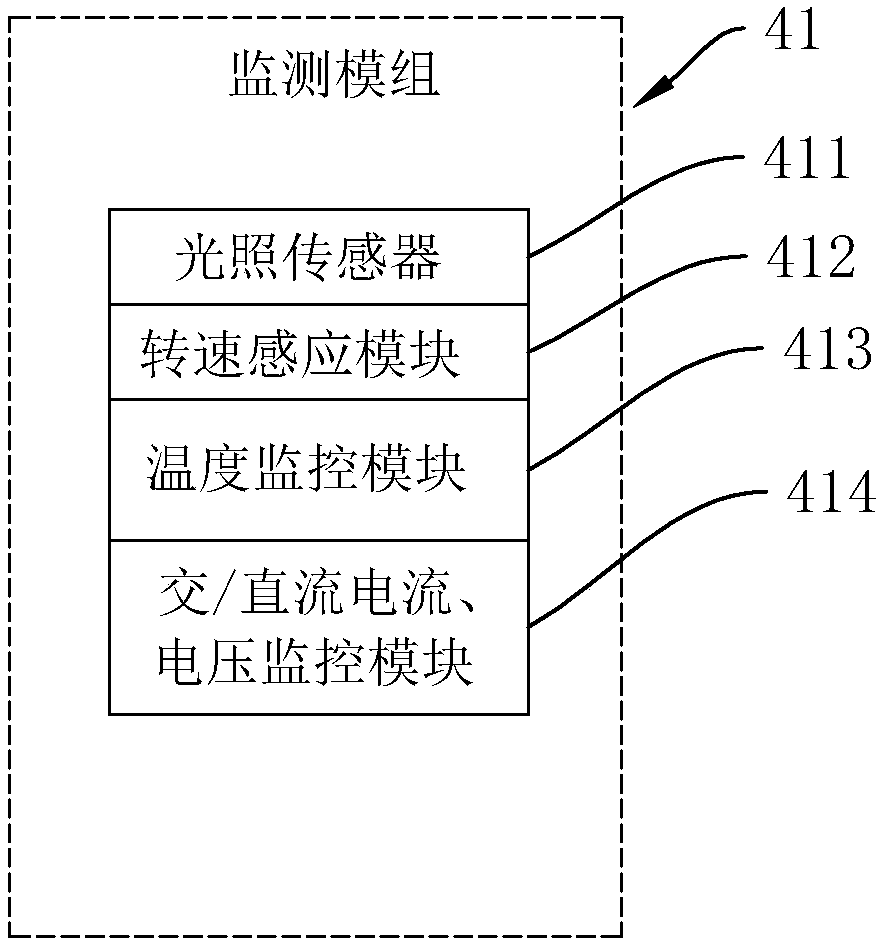
[0027] Such as figure 1 As shown, the multi-stage charging aging equipment includes a main control cabinet 1, an aging rack 4 and a load cabinet 5. The main control cabinet 1 is provided with a central control unit 2; the aging rack 4 is provided with a multi-stage monitoring module 41 for monitoring The operating parameters of the target equipment in the aging process, the monitoring modules 41 at all levels can be connected in series, in parallel or in combination with the target equipment according to the specific conditions of the target equipment, and all the monitoring modules 41 are connected with the central The control unit 2 is electrically coupled, in this embodiment, as figure 2 As shown, the monitoring module 41 is provided with an illumination sensor 411, which can be used for the illumination parameters of lighting equipment such as lamps and lanterns. 41 is provided with an AC / DC current and voltage monitoring module 413 and a temperature monitoring module 41...

Embodiment 2

[0033] When the operating current of the target device does not match the nature of the mains input current, on the basis of the above embodiments, a multi-directional control switch 44a is provided on the mains input circuit of the monitoring module 41, and the multi-directional control switch and the central control The unit 2 is electrically connected; when the monitoring modules 41 at all levels are connected in series, the first contact of the multidirectional control switch 44a is directly electrically connected to the power input connector 42, and the second contact of the multidirectional control switch 44a is connected to the power input connector 42. The circuit between the input connectors 42 is provided with a rectifier 45a, which can convert the input current of the first-level target equipment into direct current. Similarly, when the monitoring modules 41 of all levels are connected in parallel, the rectifier 45a is arranged on the On the total input circuit, the ...

Embodiment 3

[0039] When the monitoring modules 41 at all levels are connected in series, and the target equipment is AC input and DC output, a multi-directional control switch 44b is provided on the circuit between the power output terminal and the power input connector 42 of the next stage, The multidirectional control switch 44b is electrically connected with the central control unit 2; the first contact of the multidirectional control switch 44b is directly electrically connected with the power input connector 42, and the second contact of the multidirectional control switch 44b is connected with the power input connector 42. If an inverter 46b is provided on the circuit between them, the aging of the target equipment connected to the monitoring modules 41 at all levels can be realized. For target equipment such as charging piles and rectifiers, the direct current output by the upper-level target equipment can also be passed through The conversion of the inverter 46b is used for the agi...


PUM


Abstract

The invention relates to the technical field of aging experimental equipment and provides multistage charging aging equipment. The multistage charging aging equipment comprises a master control cabinet, an aging frame and a load cabinet. A central control unit is arranged in the master control cabinet. Multiple stages of monitoring modules electrically connected with the central control unit are arranged on the aging frame, and an adjustable load electrically connected with the central control unit is arranged in the load cabinet. The upper ends of the monitoring modules are electrically connected with power input connecting parts, the lower ends of the monitoring modules are electrically connected with power output connecting parts, load wiring terminals and power output terminals are arranged on the power output connecting parts, the load wiring terminals are electrically connected with the adjustable load, the power output terminals are electrically connected with the next stage ofpower input connecting part, and the power output connecting parts are electrically connected with the central control unit. By means of the multistage charging aging equipment, multiple pieces of target equipment can be aged at the same time, the rear stage of target equipment serves as the load of the former stages of target equipment, the aging efficiency can be improved, energy losses can be reduced, and the aging cost can be reduced.

Description

technical field [0001] The invention relates to the technical field of aging experiment equipment, in particular to a multi-stage charging aging equipment. Background technique [0002] The new energy industry continues to heat up, and the types and quantities of products continue to increase. The number of aging products is also increasing. But most use fixed resistors or other resistive devices to dissipate energy in the form of heat. In this way, power-on aging is performed. [0003] During the processing of electronic products, various defects will be introduced due to complex processing and extensive use of components and materials. Whether it is a processing defect or a component defect, it can be divided into obvious defects and latent defects. Obvious defects refer to those defects that cause the product not to work normally, such as short circuit / open circuit. The latent defect makes the product temporarily usable, but the defect will be exposed quickly during u...

Claims


Application Information

Patent Timeline
Patent Type & Authority Applications(China)
IPC IPC(8): G01R31/00
CPCG01R31/00
Inventor 孙开明
Owner 山东鸿卓新能源科技股份有限公司
Why Eureka
Try Eureka