Self-cooling outer rotor motor

An external rotor motor and self-cooling technology, which is applied in the direction of cooling/ventilation devices, electromechanical devices, electrical components, etc., can solve the problems of reactive power loss, increased noise, larger motor volume, and difficult dynamic balance, etc. The effect of reducing power loss, simplifying the process, and improving assembly work efficiency

Pending Publication Date: 2018-06-12
SHANGHAI HUISHEN TOOL TECH
View PDF0 Cites 6 Cited by
  • Summary
  • Abstract
  • Description
  • Claims
  • Application Information

AI Technical Summary

Problems solved by technology

However, the traditional cooling method of adding an independent fan increases the size of the motor, increases reactive power loss and noise, makes dynamic balance (or static balance) difficult, complex process and increased cost

Method used


Image

  • Self-cooling outer rotor motor
  • Self-cooling outer rotor motor
  • Self-cooling outer rotor motor

Examples


specific Embodiment 1

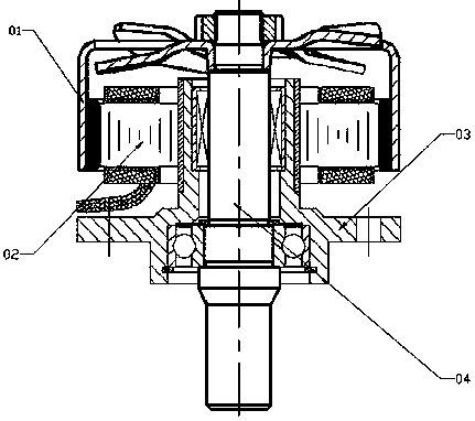
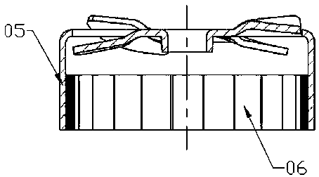
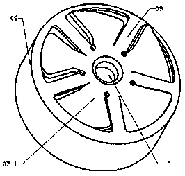
[0026] Such as Figure 1-4 , 9. A self-cooling external rotor motor, which is composed of a rotor support assembly 01, a stator assembly 02, a fixed frame assembly 03, and an output shaft assembly 04. The rotor support assembly 01 includes a rotor support 05 and a permanent magnetic steel 06, the magnetic steel 06 is adhered to the inner wall of the cavity of the rotor bracket 05, and the magnetic steel 06 is connected with the stator assembly 02 in a gap. The rotor bracket includes an outer cylinder 08 and an end cover 09, and the end cover 09 is arranged at one end of the outer cylinder 08. A rotating shaft hole 10 is provided in the middle of the end cover 09, and a number of blades 07-1 are hollowed out on the end cover 09, and the blades 07-1 are evenly distributed on the outer periphery of the rotating shaft hole 10, and the hollowed-out end cover 09 and the outer cylinder 08 together constitute an axial flow fan; there is a gap between the rotor bracket 05 and the fixed...

specific Embodiment 2

[0027] Such as Figure 1-2 , 5-6, 9, further improved on the basis of specific embodiment 1, the end cover 09 and the blade 07-2 are integrally precision casted, and one side of the blade 07-2 is connected to the end cover 09, and the blade 07-2 The other side is located inside the inner cavity of the outer cylindrical body 08 .

specific Embodiment 3

[0028] Such as Figure 1-2 , 7-9, further improved on the basis of specific embodiment 1, the end cover 09 and the blade 07-3 are integrally precision casted, one end of the blade 07-3 is connected to the shaft hole 10, and the other end of the blade 07-3 is connected to the outer The cylinder body 08, one side of the blade 07-3 is located inside the inner cavity of the outer cylinder 08, and one side of the blade 07-3 is located outside the inner cavity of the outer cylinder 08.


PUM


Abstract

The invention relates to a self-cooling outer rotor motor. A rotor bracket assembly comprises a rotor bracket and permanent magnetic steel, the magnetic steel is bonded to the inner wall of a cavity of the rotor bracket and is in fit clearance connection with a stator assembly, the rotor bracket comprises an outer cylinder body and an end cover, the end cover is arranged at one end of the outer cylinder body, and a rotating shaft hole is formed in the middle of the end cover. The end cover is provided with a plurality of hollow blades, the blades are evenly distributed on the outer circumference of the rotating shaft hole, and the hollow end cover and the outer cylinder body together constitute an axial flow fan. A gap is reserved between the rotor bracket and a fixing frame assembly; thegap between the rotor bracket and the fixing frame assembly, a gap between the stator assembly and the magnetic steel and a gap between an inner cavity of the outer cylinder body and the end cover constitute a cold air and hot air circulation passage. By using stamping or precision casting, the blades are directly hollowed out on the rotor bracket to form the axial flow fan, so that the purpose ofrapid cooling of the motor without increasing the size of the motor is achieved.

Description

technical field [0001] The invention relates to the field of outer rotor motors, in particular to a cooling method for the outer rotor motors. Background technique [0002] Due to its large torque and light weight, external rotor motors have been widely used in recent years, especially in the field of small and medium permanent magnet motors. With the maturity of precision stamping technology and precision casting technology, the manufacturing process of outer rotor motors is simpler and more convenient. However, the traditional cooling method of adding an independent fan increases the size of the motor, increases reactive power loss and noise, makes dynamic balance (or static balance) difficult, and the process is complicated and the cost increases. Contents of the invention [0003] In order to solve the above problems, the present invention proposes a self-cooling outer rotor motor, which uses stamping or precision casting to directly hollow out the blades on the rotor...

Claims


Application Information

Patent Timeline
Patent Type & Authority Applications(China)
IPC IPC(8): H02K9/06H02K5/20H02K1/27H02K7/04F04D29/38
CPCH02K9/06F04D29/388H02K1/2786H02K5/20H02K7/04
Inventor 郑智颖郑肖菲
Owner SHANGHAI HUISHEN TOOL TECH
Why Eureka
Try Eureka