Catheter and balloon catheter
A balloon catheter and catheter technology, used in catheters, balloon catheters, coatings, etc., can solve problems such as outer layer peeling, and achieve the effect of ensuring bonding strength and improving bonding strength.
- Summary
- Abstract
- Description
- Claims
- Application Information
AI Technical Summary
Problems solved by technology
Method used
Image

Examples
Embodiment Construction
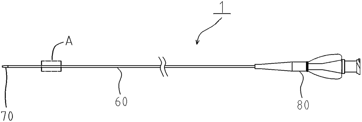
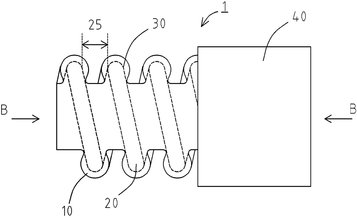
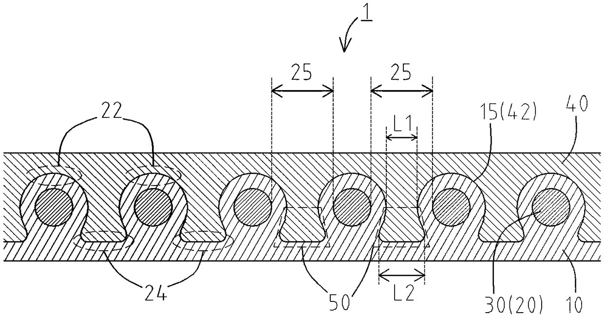
[0033] refer to Figure 1 ~ Figure 3 The catheter 1 of the first embodiment will be described. exist figure 1 In the diagram, the left side in the figure is the front end side (distal side) inserted into the body, and the right side is the rear end side (proximal side) operated by operators such as doctors. figure 2 is enlarged figure 1 A magnified view of part A of the image 3 yes means figure 2 The sectional view of the BB section.
[0034] The catheter 1 is, for example, a catheter used for diagnosing or treating a stenotic portion or an obstructed portion. Such as figure 1 As shown, the catheter 1 mainly includes a catheter shaft 60 , a sheet 70 joined to the front end of the catheter shaft 60 , and a junction tube 80 joined to the rear end of the catheter shaft 60 .
[0035] Such as figure 2 As shown, the catheter shaft 60 has in order from the inner side in the radial direction: an inner layer 10; a reinforcing layer (coil body) in which the wires 20 are woun...
PUM
 Abstract
Description
Claims
Application Information
 - R&D
- Intellectual Property
- Life Sciences
- Materials
- Tech Scout
- Unparalleled Data Quality
- Higher Quality Content
- 60% Fewer Hallucinations
Browse by: Latest US Patents, China's latest patents, Technical Efficacy Thesaurus, Application Domain, Technology Topic, Popular Technical Reports.
© 2025 PatSnap. All rights reserved.Legal|Privacy policy|Modern Slavery Act Transparency Statement|Sitemap|About US| Contact US: help@patsnap.com