High-efficiency intelligent exhaust gas treatment system

A waste gas treatment and intelligent technology, applied in the direction of steam condensation, cleaning method using gas flow, removing smoke and dust, etc., can solve problems such as hidden dangers to personal health and safety, and achieve the effects of reducing health threats, convenient disassembly and assembly, and low production cost.

Pending Publication Date: 2018-06-15
安徽蓝清源环境科技有限公司
View PDF7 Cites 2 Cited by
  • Summary
  • Abstract
  • Description
  • Claims
  • Application Information

AI Technical Summary

Problems solved by technology

[0003] The technical problem to be solved by the present invention is: the organic waste gas containing particles will be generated during the processing of the injection molding machine, which will cause safety hazards to the personal health of the operators. The present invention provides an efficient and intelligent waste gas treatment system to solve the above problems, which can Effectively collect the exhaust gas discharged from the mold port of the injection molding machine, and the structure is simple, easy to disassemble and operate

Method used


Image

  • High-efficiency intelligent exhaust gas treatment system
  • High-efficiency intelligent exhaust gas treatment system
  • High-efficiency intelligent exhaust gas treatment system

Examples


Embodiment 1

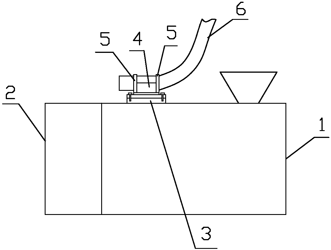
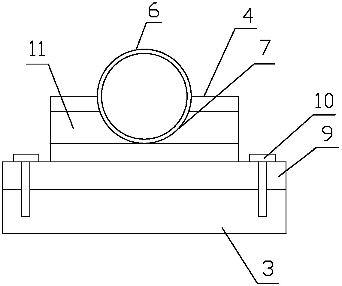
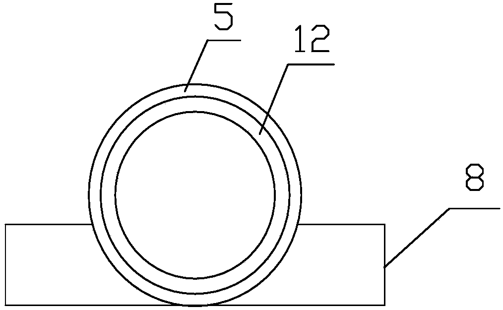
[0033] Such as Figure 1-5 As shown, an efficient and intelligent exhaust gas treatment system includes an injection molding machine body 1. A mounting base 3 is provided on the casing of the injection molding machine body 1 and close to the mold 2, and also includes a mounting block 4, a snap ring 5 and a suction The bottom surface of the mounting block 4 is detachably set on the mounting base 3, and the top surface of the mounting block 4 is provided with a semicircular groove 7 for receiving the suction collection tube 6; Two snap rings 5 ​​are provided on the transitional fitting sleeve of the input end pipe section of the suction collection tube 6, when the suction collection tube 6 is inserted into the groove 7, the mounting block 4 is located between the two snap rings 5, The outer diameter of the snap ring 5 is larger than the inner diameter of the groove 7, and the side wall of the snap ring 5 is provided with a limiting plate 8, and the limiting plate 8 is detachably ...

Embodiment 2

[0035] Further improved on the basis of embodiment 1, the suction collection pipe 6 is composed of a number of short pipes 17 which are connected end-to-end through flanges 18, and is from the input end of the injection molding machine body 1 to the output end of the connecting pipeline 13 The tube inner diameter of each short tube 17 decreases sequentially.

Embodiment 3

[0037] It is further improved on the basis of Embodiment 2, and further includes a buffer chamber 19, the side wall of the buffer chamber 19 at the top is provided with a number of air inlets distributed along the circumferential direction, and a number of suction collectors installed on the body 1 of the injection molding machine The output end of the pipe 6 is installed at the air inlet through a flange 18, and a second suction pump 21 is provided on the suction collecting pipe 6, and the air inlet where the suction collecting pipe 6 is not installed is blinded Blue seal; the top side wall of the buffer chamber 19 is also provided with an exhaust port, and the exhaust port is located above the air inlet, and the exhaust port is in communication with the connecting pipe 13. The exhaust pipe 16 is provided with an adsorption packing layer, and the adsorption packing layer is filled with activated carbon or molecular sieve solid adsorbent.


PUM


Abstract

The invention discloses a high-efficiency intelligent exhaust gas treatment system. The shell of an injection molding machine body is provided with a mounting base, the bottom surface of a mounting block is arranged on the mounting base, and the top surface of the mounting block is provided with a semicircular groove for accommodating gas suction and collection tubes; two snap rings transitionallycooperatively sleeve the input end tube segments of the gas suction and collection tubes, the mounting block is positioned between the two snap rings, the sidewalls of the snap rings are provided with a limiting plate, and the limiting plate is detachably connected and fixed to the sidewall of the mounting block; and the output ends of the gas suction and collection tubes are communicated with the input end of a cyclone separator through a connecting pipeline, the connecting pipeline is provided with a first suction pump, the gas output end of the cyclone separator is communicated with the input end of a condenser through a pipeline, and a gas discharging tube is arranged at the output end of the condenser. The high-efficiency intelligent exhaust gas treatment system has the advantages ofeffective connection of exhaust gas discharged from the die port of an injection molding machine, simple structure, and convenience in dismounting and operation.

Description

Technical field [0001] The invention relates to an exhaust gas treatment device, in particular to an efficient and intelligent exhaust gas treatment system. Background technique [0002] In the plastic processing process, a large amount of harmful gases (smoke) containing dust particles will be produced. Because these harmful gases are polluting, their direct discharge into the air will not only cause physical harm to the staff, but also pollute the environment. In the injection molding machine In the production of daily plastic products, due to the low economic added value of the products, the on-site operation of the injection molding machine requires a lot of operating labor. During the injection molding process, a large amount of yellow smoke of dust particles will be generated near the mold. Most of the smoke will be scattered in the air, and operators will inadvertently breathe the smoke. The smoke contains dioxins, which is very harmful to the human body. It destroys the i...

Claims


Application Information

Patent Timeline
Patent Type & Authority Applications(China)
IPC IPC(8): B01D45/12B01D45/16B01D5/00B08B15/04B08B5/04B29C45/17
CPCB01D45/12B01D45/16B01D53/002B08B5/04B08B15/04B29C45/17
Inventor 郭贵龙
Owner 安徽蓝清源环境科技有限公司
Why Eureka
Try Eureka