Full-automatic intelligent control electric steel pipe cutting machine device

An intelligently controlled and fully automatic technology, applied in the direction of pipe shearing device, shearing device, positioning device, etc., can solve the problems of steel pipe clamping, complex structure, low intelligence of cutting equipment, etc., to reduce the burden on workers and have a simple structure. Effect

Inactive Publication Date: 2018-06-15
贾惠惠
View PDF0 Cites 18 Cited by
  • Summary
  • Abstract
  • Description
  • Claims
  • Application Information

AI Technical Summary

Problems solved by technology

[0002] The traditional steel pipe cutting method is to fix the position of the steel pipe and use the cutting blade to rotate at high speed to realize the cutting of the steel pipe. When the steel pipe is cut, one end will be connected with the fastening device. The traditional fastening device can not only fix the position of one end of the steel pipe, but also It can also drive the steel pipe to rotate, but the structure of the traditional fastening device is more complicated, which is not conducive to the cutting and replacement of the steel pipe; the other end of the steel pipe will realize the clamping of its position when cutting. Due to the different types of steel pipes, the clamping of the steel pipes is difficult. Big problem; when the cutting equipment is not in use, its cutting blade is usually external, and the external cutting blade sometimes damages it due to accidental contact with hard materials; traditional cutting equipment is less intelligent, It needs a lot of labor, so now we need a fully automatic and intelligently controlled electric steel pipe cutting machine device. The structure of the fastening device is simpler. The clamping device can be used for clamping different types of steel pipes. The protective device can protect the cutting blade when the equipment is not in use. This kind of steel pipe cutting device is not only simple in structure but also Fully automatic intelligent control can be realized, which greatly reduces the burden on workers

Method used


Image

  • Full-automatic intelligent control electric steel pipe cutting machine device
  • Full-automatic intelligent control electric steel pipe cutting machine device
  • Full-automatic intelligent control electric steel pipe cutting machine device

Examples


Embodiment Construction

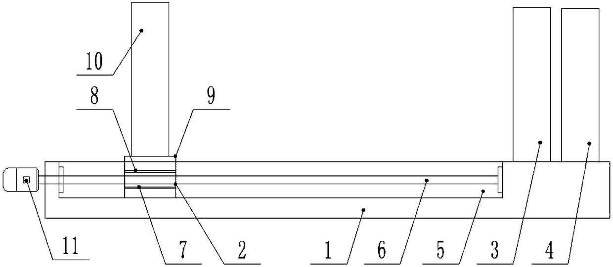
[0024] The present invention is specifically described below in conjunction with accompanying drawing, as Figure 1-8As shown, a fully automatic and intelligently controlled electric steel pipe cutting machine device includes a mounting base 1, a sliding fastening device 2 is provided above the mounting base 1 and along one end of its length direction, and a sliding fastening device 2 is provided above the mounting base 1 and along its The other end of the length direction is provided with a clamping device 3 and a cutting device 4. The sliding fastening device 2 is formed by the middle part of the upper end of the installation base 1 and has a certain length of rectangular chute 5 and rectangular chute 5 along its length direction. The screw mandrel-6 provided in the middle of the inner cavity along its length direction, the moving nut-7 set on the screw mandrel-6, the movable connection assembly-8 set on the outside of the moving nut-7, is arranged in the rectangular chute 5 ...


PUM


Abstract

The invention discloses a full-automatic intelligent control electric steel pipe cutting machine device. The machine device comprises a mounting base, and a sliding fastening device, a clamping deviceand a cutting device are arranged at the upper end of the mounting base; the sliding fastening device is composed of a rectangular sliding groove, a first screw rod, a first movable nut, a first movable connecting assembly, a rectangular sliding base, an electric control fastening device and a first rotating motor; the clamping device comprises a first frame-shaped supporting frame, a supportingplate, a bearing fixing base, a second screw rod, a guide rail, a second movable nut, a second movable connecting assembly, a long sliding block, a first clamping block, an inclined air cylinder, a first telescopic air cylinder, a second clamping block and a second rotating motor; the cutting device is composed of a second frame-shaped supporting frame, a second telescopic air cylinder, an arc-shaped shell body, a rotating shaft, a frequency modulation motor and a cutting blade. The machine device has the advantages of being simple in structure and high in practicability.

Description

technical field [0001] The invention relates to the field of steel pipe cutting equipment, in particular to a fully automatic intelligently controlled electric steel pipe cutting machine device. Background technique [0002] The traditional steel pipe cutting method is to fix the position of the steel pipe and use the cutting blade to rotate at high speed to realize the cutting of the steel pipe. When the steel pipe is cut, one end will be connected with the fastening device. The traditional fastening device can not only fix the position of one end of the steel pipe, but also It can also drive the steel pipe to rotate, but the structure of the traditional fastening device is more complicated, which is not conducive to the cutting and replacement of the steel pipe; the other end of the steel pipe will realize the clamping of its position when cutting. Due to the different types of steel pipes, the clamping of the steel pipes is difficult. Big problem; when the cutting equipme...

Claims


Application Information

Patent Timeline
Patent Type & Authority Applications(China)
IPC IPC(8): B23D21/00B23Q3/06B23Q11/06B23Q11/08
CPCB23D21/00B23Q3/064B23Q11/06B23Q11/08
Inventor 漆金枝
Owner 贾惠惠
Why Eureka
Try Eureka