Grinding work station and method for generating machining tracks thereof

A workstation and trajectory technology, which is applied in the direction of metal processing equipment, grinding machine parts, workpiece feed movement control, etc., can solve the problems of complex grinding trajectory, long debugging cycle, and high technical requirements for debugging personnel, so as to improve vector information The effect of precision

Active Publication Date: 2018-06-15
CHONQING HUASHU ROBOT CO LTD
View PDF5 Cites 3 Cited by
  • Summary
  • Abstract
  • Description
  • Claims
  • Application Information

AI Technical Summary

Problems solved by technology

[0005] This method can obtain more complex grinding tracks, which can meet the processing requirements of most workpieces, but the main problem of this method is that the debugging cycle is too long, the technical requirements for the debugging personnel are high, and the debugging labor intensity is high.

Method used


Image

  • Grinding work station and method for generating machining tracks thereof
  • Grinding work station and method for generating machining tracks thereof
  • Grinding work station and method for generating machining tracks thereof

Examples


Embodiment 1

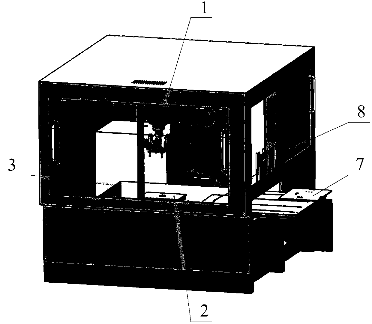
[0063] Such as Figure 1 to Figure 7 As shown, the embodiment of the present invention provides a grinding workstation, which includes: a grinding robot 1, a grinding head 2, a water tank 3, a processor, four calibration devices 4, four measuring devices 5 and a guide 6, The grinding head is arranged at the end of the arm of the polishing robot 1, the water tank 3 is arranged below the grinding head, the jig 2 is arranged in the water tank 3, and the four calibration devices 4 are all arranged On the processing surface of the jig 2, the water tank 3 is quadrilateral, and the four measuring devices 5 are respectively installed at the four corners of the water tank 3, and the processor communicates with the four measuring devices respectively. The equipment 5 is connected to the polishing robot 1, and each of the measuring equipment 5 includes: a first wire sensor 51 and a second wire sensor 52, the tails of the first wire sensor 51 and the second wire sensor 52 pass through a r...

Embodiment 2

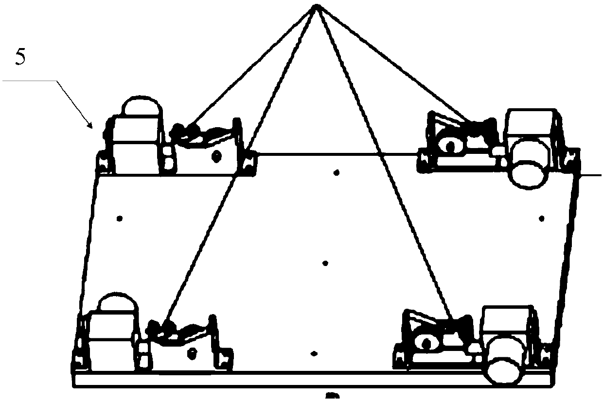
[0074] Such as Figure 4 As shown, on the basis of Embodiment 1, the first wire pull sensor 51 in this embodiment also includes: a calibration head 511, a wire clamping groove 512, a large wire pulley 513, a small wire pulley 514, and a clamping device 515. The calibration head 511 is arranged on the head of the first pull wire sensor 51, one end of the calibration head 511 is provided with a hook 54, and the other end of the calibration head 511 is connected to the first wire sensor 51 through a pull wire; The large guiding wheel 513 and the small guiding wheel 514 are arranged on one side of the first cable sensor 51, the large guiding wheel 513 is adjacent to the head of the first cable sensor 51, and the small guiding wheel 514 is adjacent to the The tail portion of the first cable sensor 51, the large guide wheel 513 is used to coil the cable, and the small guide wheel 514 is used to tension the cable; the head of the first cable sensor 51 is provided with a clamping groo...

Embodiment 3

[0078] Such as image 3 , Figure 5 as well as Figure 6 As shown, on the basis of Embodiment 2, the second cable sensor 52 and the first cable sensor 51 of this embodiment have the same structure, and are connected by a rotating shaft, and an angle sensor is arranged in the rotating shaft, which can measure the The angle between the first pull wire sensor and the second pull wire sensor, the first pull wire sensor 51 and the clamping device 515 of the second pull wire sensor 52 are respectively arranged on adjacent side walls of the water tank 3 , The first pull wire sensor and the second pull wire sensor can rotate around a fixed shaft, so the corner between the first pull wire sensor 51 and the second pull wire sensor 52 and the clamp between the adjacent two side walls in the water tank 3 same angle.

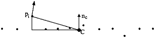
[0079] Measuring equipment 5 is set on the water tank 3, so that the simulated processing trajectory generated by the guide 6 is closer to the processing trajectory of th...


PUM


Abstract

The invention provides a grinding work station and a method for generating machining tracks thereof. The grinding work station comprises a jig, a water tank, four measuring equipment and a guider, wherein the four measuring equipment are arranged at four corners of the water tank respectively, the tail parts of first wire drawing sensors are connected with the tail parts of second wire drawing sensors through rotating shafts, hooks of the first wire drawing sensors are connected to a first point of the guider, and hooks of the second wire drawing sensors are connected to a second point of theguider. According to the grinding work station and the method for generating the machining tracks of the grinding work station, four sets of measuring equipment are arranged, and two wire drawing sensors are arranged in each set of measuring equipment, one hook is selected from each measuring equipment to form a set and is hung at the first point of the guider, the other hook in each measuring equipment is hung at the second point of the guider, and when the guider moves, the two points are used for generating two sets of machining tracks and vectors required by grinding on the tracks, and after the generated tracks are machined, a robot grinding execution program is formed.

Description

technical field [0001] The invention relates to the technical field of workpiece processing, in particular to a grinding workstation and a method for generating processing tracks thereof. Background technique [0002] At present, many industries such as home appliances, building materials, and motorcycles need to grind and process related parts. The grinding process has the following characteristics: the surface shape is relatively complex; such as mobile phone shells, notebook shells, car wheels, etc., the surface shapes of these parts that need to be polished are relatively complex. . The processing fineness of the workpiece is required to be high; the processing surface must achieve a corresponding smoothness to make the product beautiful and durable, or to facilitate subsequent processing and assembly. [0003] Due to the complex shape and high processing requirements of the parts to be ground, a lot of grinding work is done manually, but due to the rapid development of...

Claims


Application Information

Patent Timeline
Patent Type & Authority Applications(China)
IPC IPC(8): B24B19/00B24B51/00B24B49/00
CPCB24B19/00B24B49/00B24B49/006B24B51/00
Inventor 范秋垒杨伦王旭丽韩堃杨宝军郑登华
Owner CHONQING HUASHU ROBOT CO LTD
Why Eureka
Try Eureka