Electrospinning fiber injection device with controllable injection environment and control method of injection environment

A technology of electrospun fiber and injection device, which is applied in fiber processing, textile and papermaking, and filament generation, etc. It can solve the problems of high-quality production or research of electrospun fibers, lack of reliability, stability of environmental parameters, and complex equipment structure, etc. problem, to achieve the effect of simple installation, wide application range and good observation effect

Active Publication Date: 2018-06-15
连云港奥恒制衣有限公司
View PDF5 Cites 6 Cited by
  • Summary
  • Abstract
  • Description
  • Claims
  • Application Information

AI Technical Summary

Problems solved by technology

Most of the domestic spinning equipment only measures and controls the ambient temperature of spinning, and occasionally performs simple manual intervention on the humidity, such as adding desiccant, dehumidifier, etc., based on this method to spray electrospun fibers Simple and arbitrary control of ambient temperature and humidity lacks operational reliability and stability of environmental parameters, which is extremely unfavorable for high-quality production or research of electrospun fibers
A small number of high-end electrospinning fiber equipment in foreign countries has installed special temperature and humidity control devices in the spray environment, but the equipment structure is complex and expensive, which is not conducive to large-scale promotion and use in China

Method used


Image

  • Electrospinning fiber injection device with controllable injection environment and control method of injection environment
  • Electrospinning fiber injection device with controllable injection environment and control method of injection environment
  • Electrospinning fiber injection device with controllable injection environment and control method of injection environment

Examples


Embodiment 1

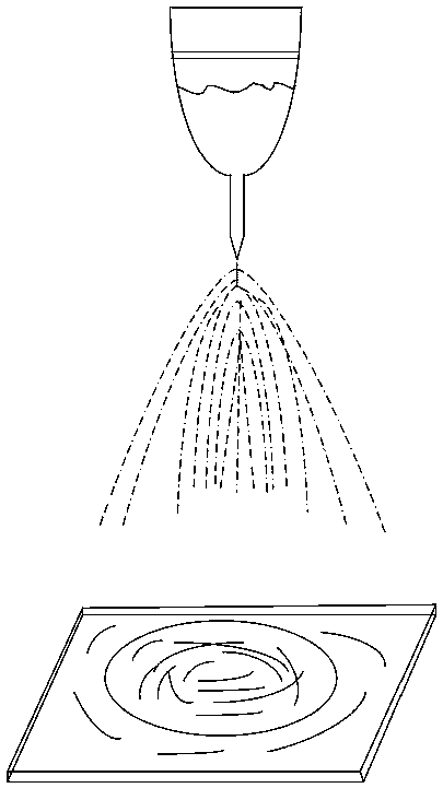
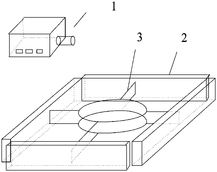
[0012] Embodiment 1: In order to solve the convenient, accurate, reliable and low-cost control of the temperature and humidity of the electrospun fiber jetting environment, this embodiment provides a combined electrospun fiber jetting environment control device based on a controllable air flow. The device consists of a constant temperature Composed of constant humidity air source, bracket, blowing slot, suction slot, filter screen, and suction fan.

[0013] Wherein: the constant temperature and constant humidity air source can output air with adjustable temperature and humidity, and the air flow is controllable. The constant temperature and constant humidity air source is a common device in the field of automatic control.

[0014] The blowing grooves are connected to the four blowing grooves by the above-mentioned constant temperature and humidity air source, the blowing grooves control the air flow to blow downward at a certain angle, and the four blowing grooves are installed...

Embodiment 2

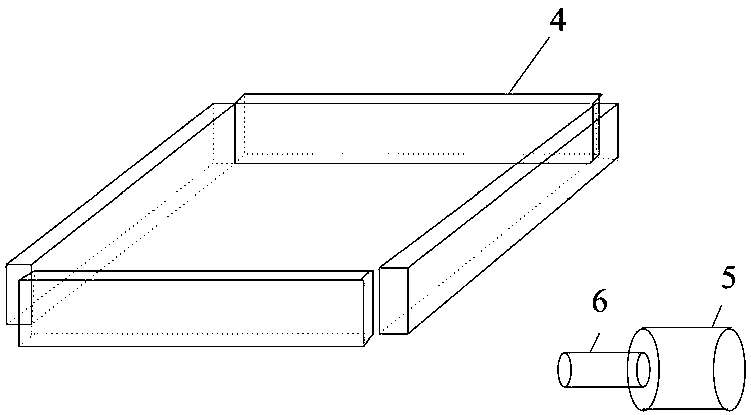
[0021] Embodiment 2: A combined electrospun fiber injection environment control device based on controllable airflow, including a blowing groove and a suction groove, the described blowing groove is a closed and hollow support frame, and the blowing groove is The hollow layer is connected to the constant temperature and humidity blower to enter the hollow layer of the blowing groove, and the side wall of the support frame is used as a guiding device for air intake to form an air curtain. The described blowing groove is correspondingly provided with a suction groove, and the suction groove It is an enclosed and hollow support frame, in which the hollow layer is connected to the suction fan, and the air curtain formed by the blowing groove is discharged by the suction fan through the suction groove. From the above, an air curtain for the air flow between the blowing groove and the suction groove is formed, so that the spray environment is formed to form a closed space, and the ai...

Embodiment 3

[0036] Embodiment 3: a kind of electrospun fiber injection device with controllable injection environment, as an independent embodiment or as the embodiment of the scheme in embodiment 2, the described blowing slot is made up of four rectangular support frames, which The four rectangular support frames are connected through the left and right side walls to form an integrated or separate connection, the upper side wall of each rectangular support frame communicates with the blowing groove, and the inner side wall and the outer side wall are closed walls. Yet at least one inner wall of four rectangular bracing frames has a transverse air outlet, and the lower side wall has an air outlet, and the air curtain is sent out from the air outlet, wherein the inner wall of a rectangular support of the air blowing groove is opened. Out of the horizontal air outlet.

[0037] In one solution, the lower position of the inner wall of the rectangular support frame opposite the horizontal air ...


PUM


Abstract

The invention relates to an electrospinning fiber injection device with the controllable injection environment and a control method of the injection environment, belonging to the field of electrostatic spinning. In order to realize thermostatic control over temperature and humidity of electrostatic spinning and make a spinning space compact and adjustable, the technical key points are described inthat an air-blowing tank is composed of four rectangular support racks; the four rectangular support racks form integrated or detachable connection through a mode of connecting left with right side walls; the upper side wall of each rectangular support rack communicates with the air-blowing tank; the inner side wall and the outer side wall are enclosed walls; then a transverse air-blowing openingis formed in at least one inner side wall of the four rectangular support racks; the lower side wall is equipped with an air-blowing opening, through which an air curtain is sent; and a transverse air-blowing opening is formed in the inner side wall of one rectangular support of the air-blowing tank.

Description

technical field [0001] The invention belongs to the field of electrospinning, and relates to a device for controlling constant temperature and humidity of an electrospinning injection environment. Background technique [0002] Electrospinning technology is widely used in the field of nanofiber material preparation. Due to its excellent physical and chemical properties, nanofiber materials have a wide range of application fields and unlimited development prospects. Countries are stepping up to improve the existing electrospinning technology or develop new electrospinning equipment. In the process of electrospinning, the charged polymer solution is sprayed, stretched, split, volatilized and solidified in a high-voltage electrostatic field to finally form fibrous properties. There are many parameters that affect the morphology and properties of electrospun fibers, such as the voltage provided by the high-voltage power supply, the distance between the collecting plate and the s...

Claims


Application Information

Patent Timeline
Patent Type & Authority Applications(China)
IPC IPC(8): D01D5/00D01D11/00
CPCD01D5/0061D01D5/0069D01D5/0076D01D11/00
Inventor 许爽丁纪峰杨亚宁
Owner 连云港奥恒制衣有限公司
Why Eureka
Try Eureka