An assembled replaceable energy-dissipating wall and a replaceable energy-dissipating structure

An assembled, energy-dissipating technology, applied in the direction of walls, building components, building structures, etc., can solve the problem of misalignment between the replaceable component connector and the embedded part, the change of the height and horizontal position of the replaceable area, and the bolt hole. Relative position offset and other problems, to achieve the effects of stable energy consumption, good ductility, and improved seismic performance

Active Publication Date: 2020-01-21
GUILIN UNIVERSITY OF TECHNOLOGY
View PDF3 Cites 0 Cited by
  • Summary
  • Abstract
  • Description
  • Claims
  • Application Information

AI Technical Summary

Problems solved by technology

However, structures often experience residual deformation after an earthquake, which can cause changes in the height and horizontal position of the replaceable area, and the relative position of the bolt holes also shifts
In the end, the connectors of the replaceable parts are not aligned with the holes of the embedded parts and cannot be installed normally

Method used


Image

  • An assembled replaceable energy-dissipating wall and a replaceable energy-dissipating structure
  • An assembled replaceable energy-dissipating wall and a replaceable energy-dissipating structure
  • An assembled replaceable energy-dissipating wall and a replaceable energy-dissipating structure

Examples


Embodiment Construction

[0065] The present invention will be further described below in conjunction with the embodiments shown in the accompanying drawings.

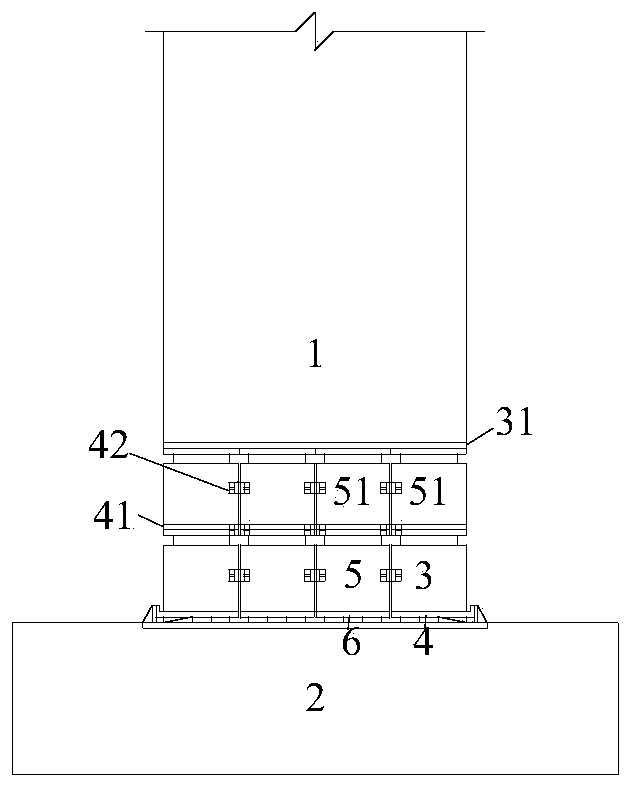
[0066] like figure 1 As shown, the present invention discloses a replaceable energy-dissipating wall assembled at the bottom of a shear wall, which consists of several replaceable energy-dissipating areas, and the replaceable energy-dissipating areas can be divided into upper areas and lower areas according to their positions. . The lower area can be divided into a lower edge area and a lower middle area according to different locations. Each upper area is composed of an upper energy dissipation section 51 and a lower connecting plate 41 below. Each lower edge area is composed of an upper energy dissipation section 3 and a lower adjustable base 4 . Each lower middle area is composed of an upper energy dissipation section 5 and a lower adjustable base 6 .

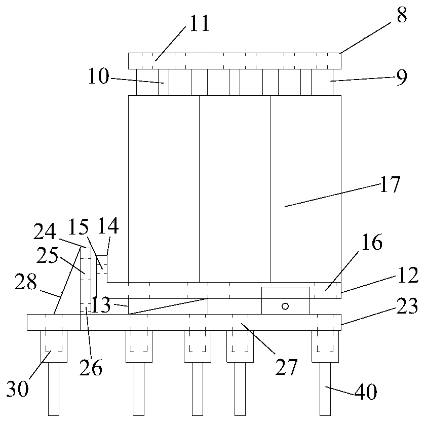
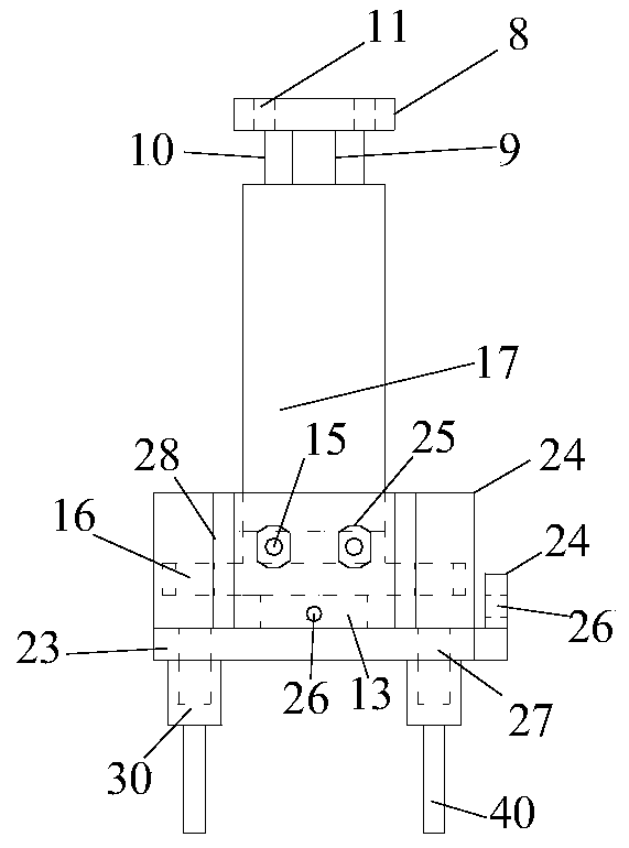
[0067] like Figure 2 to Figure 8 As shown, the energy dissipation section 3 in the ...


PUM


Abstract

The invention discloses an assembling type replaceable energy dissipation wall. The assembling type replaceable energy dissipation wall consists of a plurality of replaceable energy dissipation areas.The replaceable energy dissipation areas can be divided into upper areas and lower areas according to different locations, each of the upper areas is composed of energy dissipation sections at the upper part and a lower connecting plate at the lower part, and each of the lower areas is composed of energy dissipation sections at the upper part and adjustable bases at the lower part. The upper partof the energy dissipation wall is connected with a shear wall through an embedded part of the shear wall, the lower part of the energy dissipation wall is connected with a foundation through the adjustable bases, and the areas of the energy dissipation wall are connected by splicing steel plates. The adjustable bases have a certain spatial position adjustment function, and can be smoothly replaced when residual deformation and installation deviation occur to the structure. The seismic energy is guided and concentrated on the replaceable energy dissipation wall with superior energy dissipationcapacity by designing, so that the seismic performance of the shear wall can be significantly improved and the main structure can be effectively protected from damage. The shear wall can be quickly repaired by replacing corresponding damaged areas of the energy dissipation wall after an earthquake.

Description

technical field [0001] The invention belongs to the technical field of buildings, and relates to an anti-shock and shock-absorbing technology, in particular to an anti-shock and shock-absorbing technology for a reinforced concrete shear wall of a high-rise building structure. Background technique [0002] With the advancement of science and technology, the phenomenon of overall collapse of high-rise buildings in earthquakes has been effectively controlled, but the phenomenon of local damage to building structures is still common. After the earthquake, many high-rise buildings were partially damaged and difficult to repair. They had to be demolished and rebuilt, or the repair cost was huge and the repair period was long. Not only will it cause huge economic losses, but it will also bring great inconvenience to social production and people's lives. [0003] Reinforced concrete shear walls are one of the most widely used lateral force-resisting components in high-rise building...

Claims


Application Information

Patent Timeline
Patent Type & Authority Patents(China)
IPC IPC(8): E04B2/00E04B1/98E04H9/02
CPCE04B2/00E04H9/021
Inventor 刘其舟赵军张研
Owner GUILIN UNIVERSITY OF TECHNOLOGY
Why Eureka
Try Eureka