Supercharge Your Innovation With Domain-Expert AI Agents!

Gas transmission pipeline leaking area time-inversion automatic high-resolution positioning method

A time-reversal and high-resolution technology, applied in pipeline systems, gas/liquid distribution and storage, mechanical equipment, etc., can solve problems such as leak location and inability to achieve automatic high-resolution

Active Publication Date: 2018-06-15
DONGGUAN UNIV OF TECH
View PDF5 Cites 0 Cited by
  • Summary
  • Abstract
  • Description
  • Claims
  • Application Information

AI Technical Summary

Problems solved by technology

It can be seen that the existing methods cannot achieve automatic high-resolution leak location
[0016] A new high-resolution automatic leak location method was invented to solve the shortcomings of existing solutions that require manual adjustment of system parameters to achieve high-resolution imaging positioning.

Method used


Image

  • Gas transmission pipeline leaking area time-inversion automatic high-resolution positioning method
  • Gas transmission pipeline leaking area time-inversion automatic high-resolution positioning method
  • Gas transmission pipeline leaking area time-inversion automatic high-resolution positioning method

Examples


Embodiment Construction

[0039] The present invention will be further described below in conjunction with accompanying drawing:

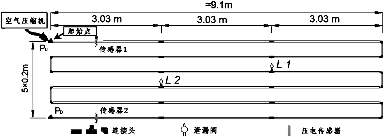
[0040] Two piezoelectric sensors, namely piezoelectric sensor 1 and piezoelectric sensor 2, are placed at both ends of the gas pipeline to detect the negative pressure wave signal generated during leakage; the leak point is located at r L , the negative pressure wave signal generated by the leak is e(r L ,t); let r L and r n The channel impulse response function between

[0041] h m (r n ,r L ,t)=a n,L,m δ(t-t n,L,m ) (1)

[0042] Among them, a n,L,m for r L and r n The signal attenuation coefficient between, δ(t-t n,L,m ) is the impulse signal, t n,L,m for the negative pressure wave at r L and r n The propagation time between , the symbol "m" represents the corresponding function obtained by measurement;

[0043] Then, at r n The negative pressure wave signal received by the n-th sensor is expressed as,

[0044] x(r n ,r L ,t)=e(r L ,t)*h m (r n ,r ...


PUM


Abstract

The invention discloses a gas transmission pipeline leaking area time-inversion automatic high-resolution positioning method. Compared with the prior art, the novel positioning method is developed. According to the method, by judging the magnitudes of resolution parameters of parts of the monitoring points, information of a leaking area can be obtained according to expected resolutions. Only relevant parameter values of parts of calculating points need to be judged, so that calculation does not need to be conducted on the whole monitoring area; and system parameters can be determined by presetting the resolutions, a great deal of manual adjustment is not needed, and application and popularization value is achieved.

Description

technical field [0001] The invention belongs to the field of industrial detection, in particular to a time-reversal automatic high-resolution positioning method for a leakage area of ​​a gas transmission pipeline. Background technique [0002] When the gas pipeline leaks, a negative pressure wave signal will be generated. By capturing the signal with a piezoelectric sensor and processing it with an algorithm, the location information of the leak point can be obtained. However, limited by the diffraction limit, the positioning resolution is often greater than one-half wavelength, that is, the -3dB region of the target image is not less than one-half wavelength. Due to the low frequency and large wavelength of the negative pressure wave, the conventional positioning technology often has low resolution when calculating the location of the leak point. However, some high-resolution imaging positioning technologies need to gradually adjust the system parameters of the detection s...

Claims


Application Information

Patent Timeline
IPC IPC(8): F17D5/06
CPCF17D5/06
Inventor 张光旻宋钢兵宋跃李冰梁家军
Owner DONGGUAN UNIV OF TECH
Features
  • R&D
  • Intellectual Property
  • Life Sciences
  • Materials
  • Tech Scout
  • Unparalleled Data Quality
  • Higher Quality Content
  • 60% Fewer Hallucinations
Learn More