Isolation clamping device special for thin film thermocouple calibration

A clamping device and thermocouple technology, applied in the field of isolation clamping device for thin film thermocouple calibration, can solve problems such as being easily affected by the external environment, affecting calibration accuracy, and compensating for wire shedding, so as to reduce the number of pick-and-place and avoid The effect of falling off and speeding up the experiment process

Active Publication Date: 2018-06-15
DALIAN JIAOTONG UNIVERSITY
View PDF11 Cites 2 Cited by
  • Summary
  • Abstract
  • Description
  • Claims
  • Application Information

AI Technical Summary

Problems solved by technology

[0003] However, since the thin film sensor is a non-standard temperature measuring device, in order to accurately measure the change of transient temperature, in the process of developing the thin film sensor, it is necessary to evaluate whether it can accurately obtain the temperature of the measurement point
When the thin film thermocouple is calibrated, its cold end and hot end need to be in different temperature fields, but its size is small, and it is difficult to realize; limited by the size of the thin film thermocouple, the thin film thermocouple must be placed in a temperature measurement furnace when it is calibrated Furnace mouth, and the open environment of the furnace mouth position makes the temperature field easily affected by the external environment, thus affecting the accuracy of the calibration; repeated pick-and-place operations during handheld calibration may cause the compensation wire to fall off

Method used


Image

  • Isolation clamping device special for thin film thermocouple calibration
  • Isolation clamping device special for thin film thermocouple calibration
  • Isolation clamping device special for thin film thermocouple calibration

Examples


Embodiment Construction

[0033] In order to make the purpose, technical solutions and advantages of the present invention clearer, the technical solutions of the present invention will be clearly and completely described below in conjunction with the accompanying drawings in the embodiments of the present invention. Obviously, the described embodiments are part of the implementation of the present invention. example, not all examples. Based on the embodiments of the present invention, all other embodiments obtained by persons of ordinary skill in the art without making creative efforts belong to the protection scope of the present invention.

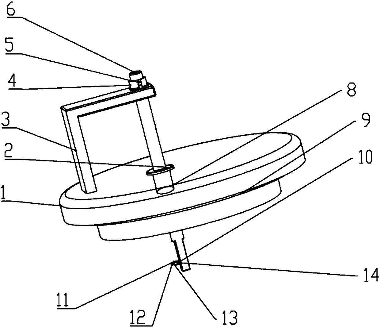
[0034] Such as figure 1 The special clamping device for thin film thermocouple calibration shown is characterized in that it includes:

[0035] Furnace tube cover 1, which is fixed on the upper end of the temperature measurement furnace furnace tube;

[0036] Γ-shaped bracket 3, one end of which is fixed on the cover surface of the furnace tube, and the other ...


PUM


Abstract

The invention discloses an isolation clamping device for thin film thermocouple calibration. The isolation clamping device comprises: a furnace tube cover fixed to an upper end of a temperature measuring furnace tube; a bracket having one end fixed on a surface of the furnace tube cover and the other end being fixedly connected to a guide barrel; the guide barrel whose center is fixedly aligned with a center position of the surface of the furnace tube cover; a sliding rod extending from the furnace tube cover and having an upper end being placed in the guide barrel, wherein a position of a thin film thermocouple to be tested in the temperature measuring furnace tube can be adjusted by changing the length of the sliding rod inserted into the temperature measuring furnace tube; and a clamping structure which is fixed on a lower end of the sliding rod and is capable of adjusting the strength of clamping the thin film thermocouple to be tested. The clamping structure is fixed on the lowerend of the sliding rod and can adjust the position of a sliding clamping sheet so as to clamp the thin film thermocouples to be tested of different sizes. The invention has the advantages of realizingseparation of a cold end from a hot end of the thin film thermocouple, reducing the adverse effect of an external environment on the stability of a temperature field in a temperature measuring furnace, and avoiding falling of a compensation wire.

Description

technical field [0001] The invention belongs to the technical field of temperature measurement, and in particular relates to a special isolation and clamping device for calibration of thin-film thermocouples. Background technique [0002] With the rapid development of science and technology today, the low-dimensionality of various materials has become one of the important trends in the development of material science. A large number of thin-film materials with different functions have been used more and more in industrial production, and thin-film thermocouples The temperature sensor is a new type of sensor that appears with the development of thin film material technology. Compared with ordinary bulk thermocouples, thin-film thermocouples have typical two-dimensional characteristics, and the thickness of their thermal junctions is on the order of micro-nanometers. Therefore, they have the advantages of small heat capacity and rapid response, and can accurately measure trans...

Claims


Application Information

Patent Timeline
Patent Type & Authority Applications(China)
IPC IPC(8): G01K15/00
CPCG01K15/005Y02E30/30
Inventor 崔云先杨琮牟瑜刘秋雨
Owner DALIAN JIAOTONG UNIVERSITY
Why Eureka
Try Eureka